


(Story)
m/c history
project
events
Hardware
Software
People
Media
Support
Future
Links-
The ICT 1301 Resurrection Project.
The Project Diaries
( or BLOGS, if you insist! )So what is News this Edition!
A major fault with the machine, looked as if the OPEN DAY was going to have to be cancelled, but
we managed to pull the machine back in time to deliver over 7 hours of public viewing.
Below is all the gorey detail !Here in reverse Chronological Order are the diaries for
2009 right back to 2003, when we started.
Episode 114:- 5th August 2009
Today it is time to return to the primary aims of the project and work on the high speed transfer interface resumed. Signals that last year were giving us problems are now linked in via co-axial cables and we are seeing signs of success ! The machine ran from about 13.00 to 17:00 whilst we worked on the resolution to the interface problems. At any point in time we were expecting the old problem to return, but by close of play the machine was still running well. The only thing that got caught today was brought in by the cat who lives on the farm, looks as if his hunting skills are better than ours.Episode 113:- 22nd July 2009
This day started with us setting up a way of identiying just what caused the pre open day problems.We have now made it possible to isolate every branch of the failing signal in an attempt to find the cause of the problem. Its just a big logic mouse trap and we are awaiting the return of the problem to cure it once and for all.
The day closed with a full run of the machine and although 5 decks were possible we limited the run to 4 and all the peri's we could fire up! But the problem did not return, so we left our big mouse trap set up for another day !
Episode 112:- 12th July 2009
Up early and out the door at 06:30 to ensure the event goes off.However I nearly stopped the open day happening, as having set some caution tapes to mark off an area, I ducked under the tape to exit and cut my head. The medical help was rapid and effective which meant we only started a little later than usual. But it does mean that we can add real blood to the effort today !
" Link to the 2009 Open Day Page "
Thanks to Stuart Fyfe, Morgan, and all who showed up to support us on the day
including some of the original engineers, always a real pleasure to meet up and talk over old times.
hard to say how many people visited but estimated at over 310
Episode 111:- 8th July 2009
Pre open day nerves are starting to show and its all hands to the pumps to finalise the setup. News today is that we have a ring main installed around the machine, to feed test gear and lighting, also we have an extractor fan!Whilst working on the surrounding area today we monitored the power supply that failed on the 1st and it stayed steady all day long !
Episode 110:- 3st July 2009
Well today is a special day, the open day is close and we do not have a working machine to show the public, so I am here at the project trying to fathom out two things !1. What has happened after the ' Burnup ' we suffered 2 days ago ?
2. How can we get the machine back to a point where we can at least load and run programs ?
So a check of all the connections showed that no shorts could be found, and further that all the signal levels were connected. A check of the power however showed a miss match between the minus 6.3volt (a) supply and the minus 6.3volt (b) supply ? had this got too far out of spec and blown the a board in bay 11 ??
1's stream bistable in 5A8 - cr's ok now , but only a few orders could be obeyed !
digging further the machine is stopping too early to terminate long functions
After much chasing of our own tails we worked back to the board that had burnt up, and discovered that it consisted of two elements. The other element in the board used to replace the damaged board was defective ! ( ever get the feeling you cannot win sometimes ? )
Now at least a larger set of functions run to completion! And we may just have enough CPU to run the OPEN DAY after all. ( Phew ! )
Episode 109:- 1st July 2009
After loading my car up with items for the openday on the 12th I was a little later than usual arriving at the project, but as I entered I could hear the machine running as Roger worked on the demo program. He was working on the code that produces the clearwrite paper tape that the machine produces for the visitors. I unloaded my car and started going through a checklist of items we may need.All seemed to be going well and after the last visit the prospects for the event were looking good. The day was quite hot and walking outside to review the layout of the entrance area I needed a good sunhat on, however on returning to the machine a whiff of hot paxolin greeted me, I shouted to Roger 'Something Hot' and we started sniffing like mad and moving around to isolate the source. Our noses agreed that it was coming from bay 6 and as that is one of the main CPU bays the power was turned off, the covers removed from both sides of the CPU and we isolated the lingering smell to logic Rack B.
No sign of any discoloured components could be seen, but access here is limited and the boards are very tightly packed together. Eventually we had to turn the power back on and try to locate the source again, we had got close and the package in Bay 6, Logic Rack C position ?? proved to be the culprit. A small inductor was grossly COOKED and BLACKENED, thinking that we had got lucky we replaced the board and powered up with caution, only to be greeted with the same effect after a 90 second period.
where it dumped current into the CPU logic.
We had a short circuit somewhere in the heart of the CPU, whatever the problem the output on pin 25 of this package was bieng damaged. So it was into the Wiring and Address books and the signal seemed to go to lots of places. Putting together a list of outgoing connections we isolated 5 signals to the far end of the CPU and tried again, with the same whiff of death from our logic with in about 90 seconds. Another try found 3 more connections listed, and still the problem remained.
Now we were sure we had got all of the destinations of the signal isolated we had to start considering a wiring short somewhere. A meter showed that the outgoing pin read very close to a short circuit to earth and we left the meter connected and started unsoldering connections as the signal moved from bay to bay. At last with the link disconneted between bay 5 and bay 11 the short vanished, so we knew it was on the outgoing side somewhere in bay 11 and the only valid destination in that bay had the pin already isolated.
We were now faced with removing the complete logic rack which housed the board, not an easy job to undertake in the somewhat stifulling heat but there was no other option. Removing the 50 or so wrapped connections freed off the rack and it was fully withdrawn, taken outside and examined in the bright sunlight. It may be a disappointment to you dear reader, as well as to the both of us but no sign of any short could be found, the rack was vacuumed cleaned and after the odd bit of bird dropping was removed and given another close visual inspection. A test with the meter showed that the fault no loger existed, a further test showed that the short was not in the remaining CPU so it had vanished. A few short, sharp four letter words may have escaped our lips at this point, which may have reflected the reference to bird droppings above. Inspection of the bay with the Rack removed shed no more light on what the cause of the short may have been, but did show some more of the dreaded birds nest which gave us problems many years ago.
After we assured ourselves that we had cleared the problem, ( and the birds nest ) we started to put the rack back together, a slower process than removal and carefully checking each step as it was a tight fit with multiple connections on both the left, right, top and bottom of the rack. So some 90 mins later we had the rack back in place and powered the machine back up and started sniffing like mad for about 5 mins until we felt we could detect no trace of further burning. Then it was time to reconnect all of the isolated signals and try to run the machine, flossie seemed to power up ok, but we soon discovered the we were now suffering from another problem, the control registers were getting corrupted when moving between Control register two and one. At first the 4 bits were gaining and we isolated that to a bistable in ?? which was changed, on the next power up the 4 bits were good but the 1 bits started failing, which had been good before.
A long time was spent trying to understand the new fault with reference to what we had just done, the logic in bay 11 is all to do with clock counting from the drum and it does inpact on the control registers in that the current drum address can be transfered into the control registers during an update half way through a drum transfer. Did we have a problem that was modifying the control registers when it should not ??? . We decided to let the machine cool down and will check the state of play early tommorrow morning, during this time the Audio/Visuals for the open day were checked and at least we have the information prepered for visitors.
I left quite late, after 19:00 hours and it seemed that we had gone from a working machine at about 12:00 hours to a broken machine a few hot and sweaty hours later. At this point the open day is not going to happen as we do not have a machine to demonstrate. ( ALL PART OF THE JOY AND TEARS OF COMPUTER CONSERVATION ) I told myself as I drove home, and muttered a few 4 letter words just to let off a little steam. The day closed for me with good news as I was very late back and my dinner had not been fed to the dog, but only because we do not have a Dog !
Episode 108:- 24th June 2009
The project today is getting close to completing the preparation for the open day and at first some work was undertaken tracking down the signals from the card punch, and after a half days work the card puch could read all eighty brushes, most of the problems were down to broken wires between the punch and the input logic rack where the contents of the card are read after punching to check the validity of the data.The last item on the Punch was the contactor again ( this has haunted us for a few years on and off ) but this time a small securing screw was found to be loose in the magnetic hoop used to pull the contactor points into place, another fix to a long term problem, we hope.
We then moved on to the magnetic tape decks and I worked on one or two of the decks whilst we execercised the CPU with the latest verison of the demo program. Our line up of eight decks has given us the probability of starting the open day with 5 of the decks working, which is a considerable improvement on the 2 or 3 we have had in the past. The execessive use of the decks may be a problem though as the heat given off will raise the temperature quite rapidly, and with only small fans at cooling at present we will have to be cautious.
Episode 107:- 17th June 2009
The next item today was to try to find out what the state of play was with deck F, this deck seems to behave in a strange way and to investigate we had to reach the back of the deck. So it was into the power supply from the rear, accessed by dropping down into the area from the top, and the first thing we found was that the deck had been modified ?Eventually we found the diagram for the changes made by Galdor and a quick shorting link allowed the deck to not only run up but we could read data from it, after the pinch rollers were setup ! So we are approaching 3 decks working after the big shuffle around over the winter of 2008.
Episode 106:- 3rd June 2009
With a line up of eight decks we started to work along the problems these presented, the actual cable connections had to be established and we have two reliable decks out of eight in a line. Unfortunatly deck C was working well and our best deck so far, but now it runs away on read and implies a deck logic problem which will require the whole CPU to resolve, and fault find. Apart from some signal lines which need to be fault found the work on the Card Punch has improved the reliability considerably. The unit is now responding to program control and almost seems to be a fully functional unit.Episode 105:- 3rd June 2009 2009
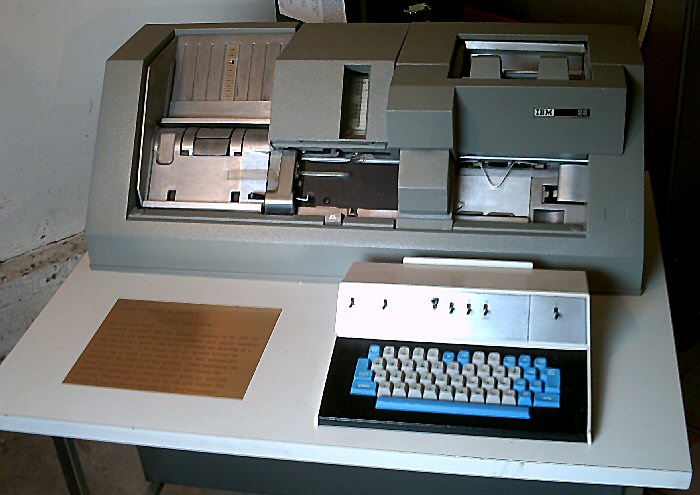
We are having extra lighting installed today so whilst awaiting this I changed roles due to the delivery of an IBM 029 Key Punch all the way from US of A, so putting my old Data Processing Enginers hat on we started to tackle the problems of getting a 110volt a/c 60hz key punch running on english 250volt 50hz mains. Fortunately the manual came with the machine and we soon found that we could change the mains input strapping to accept 250 volts. As I first try it was logical move, the transformer strappings implied that the 110volt motor would hang off of a winding as if it was an auto transformer. Having made the changes we all moved well away from the machine and flipped the mains on and off again quickly and 'Yes' it blew the fuse in the plug.Head scratching followed and the diagram was reconsulted, after a while we convinced ourselves that the motor was getting 250volts not 110, so we could strap the transformer but not the motor ! Was this another brick wall ? Roger vanished and returned with most ( but not all ) of the card bed from an IBM verifier, but it included a 250volt motor which although it was a little larger looked as if it would fit on the 029's frame.
Now we were left with the 48volt relay supply which was quite happy to settle at 41(ish) volts. However this was enough to allow the mechanism to feed cards and if we were lucky it would space cards along the bed, but only sometimes and very intermittently.
Information suppled from the 1401 project suggested that the Resonant Transformer design of the Power supply was excellent at stabilising a supply, they have several in the 1401 and they work well. This is true if the mains is 60hz US standard but not UK 50hz !
However enough works so that we could remove some problems and could confirm that this was going to be a superb addition to the projects collection. Also work continued and the mechanism had old punched card chads removed and parts of the machine freed up after its long transatlantic journey. There still remains the issue of the relay supply but we will try to resolve that in due time. Another gain from the work today was the addition of extra lighting as Richard fitted up two lights to improve illumination in the work area.
104th Episode:- 20th May 2009 2009
Today we recovered from the Visit on the 12th and the first item was to repair a magnetic tape hub, which had failed during the Demo laid on for our visitors. The next item was to load and run ' Images ' of store test packs, these images were supplied by ACONINT many years ago, and it was with much relief that tests such as AA10/11 loaded via Rogers Serial Boot Loader and ran. We continued with the B tests and the C series covering the CPU and order code. We do have a failure on Sterling functions which we have not investigated, but we have a lot more confidence now some of the official tests have run successfully.Further work today was to set the card reader to reject each card and not to try to use the upward stacker, we will be reading card packs soon and we do not wish to risk crunching up cards in this stacker.
Then we moved onto the Card Punch and in trying to set up the CAM timings we first checked the Continously Rotating cams and hit problems with respecified timings which were only penciled onto diagrams. Both the settings and the modifications were a little vague and we even had to replace one cams arm as it was damaged, the cam itself ( as it was worn )
After that problem we moved onto the Cluched Cams, these only rotate whilst the mechanism is transporting cards. Try as we might we were unable to make sense of the huge errors we were getting with these cam timings, eventually the penny dropped that the gear train driving the cams was out of step with the main gearbox timing, by moving the cam timing shaft one tooth relative to the main mechanism most of the timings fell into spec. However these timings still need to be set correctly and we just ran out of time today.
103rd Episode:- 12th May2009 2009
and also the Computer Conservation Society Visit.
The whole day is on its own page here :-
The 12th May 2009 Computer Conservation Visit
102nd Episode:- 6th May 2009 2009
 -
-
Another problem for today was the inability to get the alarm to sound when the machine was in stopped mode. The red light came on but not a sound from the monitor speaker, various logic boards were changed and the problem was starting to look silly as basic logic rules were failing. We started to suspect the clock speed as the machine had been used for a long while on variable not true DRUM speed clock, sure enough the clock had sneaked higher than one mhz, the scope said about 1.075 mhz. I have made a note to bring a frequency meter next visit !
101st Episode:- 22nd April 2009 2009
Today was the return to work on Deck E which has a very funny fault and again is looking like power supply failure ( this time the -24 volts ). Despite many attempts today the deck still fires actuator drive valves randomly.100th Episode:- 8th April 2009 2009
Issues in order today were Mag Tape deck D was failing to drive tapes, after much chasing the 400 volt line to the Actuator was found to be bad. This in turn was chased down to a failed (leaky ) Capacitor in the power supply. Once again a spare was available and after much careful work the deck was restored to life.We then moved on to Deck E which has a very funny fault and again is looking like power supply failure ( this time the -24 volts ). The day finished with a quick investigation into a missing column 2 from the Card Punch Sensing brushes, Time ran out but Roger confirmed that over the Easter weekend that a broken wire had been repaired. Also that he had succeeded in starting to get the serial bootstrap working at 9,600 baud, well done Roger.
The day finished with us agreeing that the April edition of the site would reflect that we had moved from 91 to 93 percent on the original Aims and that we were now moving forward again for 2009.
99th Episode:- 25th March 2009
First item today is the failure of the machine to run Multiply commands when cold. The machine actually locks up, after a lot of scope tracing of logic levels when the machine locks we found that the output of the mill ( adder ) was giving a randon insertion of 2 bits. Logic baord in found to be on temporary rubber connector, OOpppss ! looks like we forgot this from last year.Also another problem isolated where Digit 5 bit 2 was dropping out of the C Register, Logic board changed and problem solved.
Work by Roger after I departed today also showed a problem with the 1300 assembler used to prepare the punched tapes. Once that was fixed we had clocked up 4 fixes today, so good progress all round.
98th Episode:- 3rd March 2009
Much work on the Card Punch, this has been overlooked whilst we worked on other devices. The Main Motor drive contactor, has been cleaned up and adjusted, the strange status problem where the Punch would not become ready was ' eventually ' traced to a defective realy coil ( Relay 12 ) A new coil was fitted and now we were able to continue fault finding.Next problem was a maladjusted ( Card In Hopper ) switch. Now we can load cards, make the unit ready and may be able to read cards as well. But one last problem with a small PCB which is designed to power the punch motor down after about 120 seconds, No spares for this, and we finished the day giving up on this fix.
A short attempt to adjust the Paper tape reader head just proved we had a few more problems, system still not run a multiply command without locking up most of the time.
97th Episode:- 28th Febuary 2009
Roger's logsWhilst waiting for the computer room to come up to 55F I re-seated the punch die block, reconnected Decks B and E to their own electronics and swapped the four thyrotron valves in deck E to see if that solved the problem.
I tried deck E and it seemed worse. The large EL C3J valve lit up at random intervals making the sound of intense arcing. This is the only valve I had not changed. Back to deck B, loaded a tape and tried reading it. This time it mechanically went through the motions but is slow motion!
I tried another read, a couple of backspaces and reads, a rewind and an unload. All in slow motion and incorrect data being DMAed into the core store. The I noticed the vacuum motor was not sucking - I had forgotten deck B has long had a minor problem. A quick tap on the relay and all worked great, so after all there was not anything wrong with deck B's electronics after all. Maybe removing and replacing the plugs in the drum junction had fixed the fault.
I tried out the punch program once again and found the CPU was stopping with an IAS to CR (core memory to control register) error on loading the word 410115584105. Seems to be objecting to the data itself. I stored zero in word zero and jumped to it, no problem. I stored 9 and then 5 in there and both gave errors on the jump. maybe something to do with the parity checking or with the detector for digits greater than 9, i.e. hex A to F.
I connected deck C to the electronics of deck E and it worked perfectly, so we have two working decks, nearly back to where we were before all the upheaval.
I looked in behind the punch control panel and discovered a broken 6v bulb in the 'hopper nearly empty' and no bulb at all in 'stacker nearly full'. I put new 6v bulbs in both but neither lit up when I operated the micro-switches manually. Suspecting a power supply problem, I looked at the punch's PCU and NO lights were on, but the voltage variation showed all voltages were present. Put in three new bulbs and still nothing. Turned out they were all blown, but then I did only pay about 3p each for them on eBay. The next three were all fine. The pilot bulb of the 3v supply worked, the stacked nearly full worked but the hopper nearly empty light did not, seems like a problem elsewhere. The other PSU bulbs also replaced, all OK except the minus 20v (A) which seems to have no power to the lamp holder, maybe the dropper resistor is open circuit.
96th Episode:- 25th Febuary 2009
Roger's logsI managed to do a little more on Flossie today.
Two weeks ago one of the decks made a burning smell, though I can't remember which. Whilst waiting for for the temperature to get up to 55F I risked the decks without Flossie at the official 50F limit.
I can tell you that not only has deck E had a tape mounted on it for the last 30 years but that the upper pinch roller has been activated all that time. The reason for the smell could be the fact that the capstan drive belt had been stuck to its rollers and so the drive motor could not turn. The aluminium of the belt tensioning pulley and the small roller had white rusted to the belt. A little force allowed it to turn by hand. The motor started and then the belt stuck again. Turning it by hand for a few full revolutions and it seemed a bit more free. I tried the motor again and it stalled again but then with a shower of aluminium oxide it came back to life and ran well. The vacuum motor sucked the tape up and the swing arms activated and all seemed well mechanically. Electrically the pinch rollers would not move and when pushed on manually, the spool motors would not move. Maybe it need some power from Flossie to make this work.
Later it was warm enough to power up Flossie. Deck E then responded to a backspace command, though it then lit its overload light. Resetting the overload between operations and I could then read, backspace and rewind, though I stopped it before the start of tape just in case, as the other decks would not go forward at all. Mulling things over I decided to plug our most promising deck (B) into our most promising deck electronics (E). On powering up again, deck B broke the splice of the leader tape to the main tape. Worth another try I thought. I loaded another tape and this time deck B would read, backspace rewind and unload. I know writing would not work. I did not check the data read in detail but there were the customary Cs and Ds in the tape label block and it finished with Fs so all in all it looks like after all the upheaval, we have ONE working deck and set of deck electronics with which we can hopefully debug the other decks and sets of electronics (and possibly connecting cables) by using the known good parts.
I moved on to the card punch reading facility. My program was still in core and I noticed the bug which had caused it to run continuously instead of reading a single card. In keying in the program manually I had got one address field wrong. I used my test card reversed to test the other columns. It looks like columns 30 is stuck at zero but possibly I wrote the results down wrongly. I set it up to continuously read cards whilst I looked at the signal from the column 2 which is definitely stuck as a one. The punch wrecked before I could get to the 'scope. I removed the wrecked card by pulling the die out but after putting it back the punch would not start no matter what I tried. No chance to double check the results I wrote down earlier. Time to turn off for the day and seek Rod's advice, or as a last resort I suppose I could find the operator's manual and read it :-)
95th Episode:- 22nd Febuary 2009
Roger's logsJust a note to say what I've been doing with Flossie.
I have bought some wedge lamps, 32 x 24v yellow, 37 x 17v orange and they came with 15 x 6v grey ones, all for 7.20 which is not bad for the rare 17v ones alone.
I have also picked up seven boxes of 14.5 by 11 listing paper, 70 gsm
I was thinking about the white plastic boxes I have been using for spares. They have clear plastic tops. I realised I could use one drawer of the plans chest to hold a load of them so I would then be able to see what's in them all at a glance. One box had a seized hinge and the top broke off. In moving the stuff to another box, under the other stuff (capstan drive belts) I found a polythene bag with tiny little oblong cubes, if you know what I mean, each with two terminals and some with yellow dots.
These might be the card reader photo cells or paper tape ones maybe.
I have spent some more time unfolding the technical drawings and putting them in the plans chest. It sounds like a quick job but there are SO many drawings you soon get a back ache. I also glance at the drawings and sometimes learn something new. Today there was a drawing of the punch which was specific for two machines, it said London University ICT serial No 6, GEC serial No 7 and Rothams ICT serial No 8 and GEC serial No 12. So that's one more serial number identified. The customer list says the Rothmans machine went to Australia. Surprising that it was practical to export such an early machine, says a lot about ICT field engineering's organisational abilities.
By the time the computer room was warm enough, I had just under 3 hours to use Flossie. The core was OK apart from one bit consistently a one in every word of barn door 2 but I didn't need words 400 to 799. I had punched a paper tape (on my Mac) of a program I wanted to run to be loaded using the minimal 3 word bootstrap. It would not load. I don't think it was the tape because there were about four different places where it stopped in the reader. I could not see anything wrong when I stepped through the bootstrap. Maybe it was still too cold. Maybe the CPU maybe the reader.
I powered up drum one and it did produce a clock, so attaching drum 3 has not messed that up. Initial orders did not work. Reading a single decade, the first instruction was OK but the rest seemed to be messed up. I hand keyed a small program to read one card through the card punch check read brushes, in preparation for reading cards with non standard card codes. After the customary knock of the contactor with handle of a hammer, the punch sprang to life and read a whole deck of cards, though it was only supposed to read one card into core. Anyway I arranged for a card with data on it to be the last but two card in a deck and let it stop at the end of the deck, so the test data was left in core. I noted down the pattern in core and shut Flossie down. Afterwards I found that most of the data was correct, though because I fed the card the wrong way, columns 1 to 33 were blank hence not tested except that column two always read as a one.
Remembering that back in the early 1970s, when the operators told me my deck of cards could no longer be read by the computer, they advised me to use an old fashioned card reproducer to copy my cards. I think the old machine used similar technology to Flossie's punch and had no problem at all so the punch might be a more reliable way to read old cards that through Flossie's proper card reader.
94th Episode:- Febuary 2009
Roger's logsMore news from Roger that the Mag Tape Decks are showing signs of starting to work again, and the next item in line for action on the 11th of March is the Card Punch !
93nd Episode:- 11th Febuary 2009
Today is the first day that I had seen the results of all of the work undertaken over 2008/2009 winter first hand. The space around Flossie is impressive and the next open day will be a better experience for the visitors, the helpers and Flossie herself as we will be able too cool the room easier. The other event today is the visit of Dr David Hartley and Hamish of the Computer Conservation Society.The Second Computer Conservation Society visit.
After our friend's departed we were able to get Flossie to run and the standard multiply yardstick to check her basic functioning. The year on year improvement is now showing, and we were able to start on the first problem of the year.
The Card reader Read Cell for the '11' position was not working, it was soon traced to a failed transistor on the cell amplifer board in position CRA23. A new (Second Hand) GET872 was soldered into place and solved the problem. Moving on we found that some or all of our Mag Tape decks did not respond, it is however very early in the year and the cold was taking its toll.
Whilst testing all the Mag tape drives one deck in the line had a tape loaded ! In all all Innocence I asked Roger how long the tape had been on the deck. ( thinking about a few days perhaps ? )
The answer came back from Roger, " Oh about Thirty Years I suppose " and that dear reader has to be the punch line of the year from this project, for we are only 3 years away from Flossie's fiftieth birthday !
92nd Episode:- Febuary 2009
Roger's logsStill snow on the ground but Richard and Gordon drove down and we got the card reader moved in slightly closer to the console by taking it off its castors and lowering the jack feet so it fits under a lip on the console. The power supply rack and card punch shifted along with it giving us an extra inch or so between the punch and the magnetic tape drives.
About 60 logic connections between the third drum and the drum junction were soldered up so we should now be able to power up Flossie when we can get the computer room up to 13 degrees C (55 Farenheight).
The covers for drums two and three have not been fitted since Flossie left Surbiton around 1978, and even before that they had been cobbled together out of covers for other units, bits of wood and pop rivets. Most of the hinges and top covers were fitted to the third drum and the doors sorted out for the best fit. The end cover will need a couple of spot welds re-done but it looks OK. The corner cover strip was fitted between drum one and the front drum. We will need to modify drum 2's end cover as it fouls the doors if we use the bolt holes as is. There is a 30mm gap between two of the doors which we will probably fill with a piece of wood painted appropriately. Long term we will want to make some new doors and top covers, especially if we fit a fourth and maybe even a fifth drum.
91st Episode:- January 2009
Roger's logs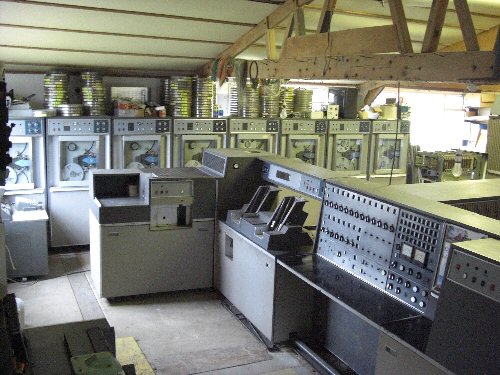
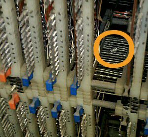
Here is a view of the new layout which is the background to the 2009 Openday and the new Workarea.
I wanted to find out what is wrong with the card reader's decoding logic and maybe fix it. With one day of reasonable temperatures forecast I left two fan heaters going overnight. In the morning I put in a third one. By 1:30 p.m. it was up to 57 degrees F (14 C) at the drum junction and 56 at the console.
I turned the card reader to safe, turned the drums off, pressed the on button and got a clock straight away. Checked for smoke, no problem. The printer delay turned the printer on and the print hammers started their usual random firing, gradually reducing to nothing.
I checked the control registers would count, they worked fine. I cleared the core and read it back. About a half a dozen errors. I set every bit and more errors. Every digit 1 bit 1 from 1600 to 1999 failed. I looked at barn door 5 and that bit was on rubbers. Wiggled it a bit and that fault went away.
Later on when fully warmed up, we had a full complement of core memory. Not a bad start to 2009.
I found a card with the normal character set punched in it. Before I started the machine I had put it in the card reader, manually activated the picker knives and turned the machine by hand until the first character was at the main reading position. I hooked the Gould scope up to the output of the '1' row amplifier. Winding the reader back and forth and the signal could be seen changing. I tried to do the same with the '11' row. No change. Tried adjusting the adjusting pot. Still no change. The scope then went wrong. It has just two LEDs illuminated but the CRT was blank. This is the first year I have not brought it in for the winter. What to do now?
I thought I'd try out the Hewlett Packard scope which has not worked for quite a long while. It worked just fine. Neither the '10' or '11' row seem to work, though the working '1' row uses the same amplifier brick. There are a lot of Galdor patches on that part of the PCB carrier so I decided to not go in like a bull in a china shop and think about it a bit. I tried scoping the photo cells outputs but did not see any change there either. I powered up the punch and it still fed cards (after the customary knock on the three phase contactor with a screwdriver handle).
We bolted the third drum onto Flossie and levelled it up. I still have the earth connection, data connections, 3 phase power and the contactor's remote control cable to fit. Then we can at last fit the kick plates and
covers which have been lying around for the last three decades.
I have had an old plans chest in an old (Tudor) barn for many years and never had space to install it in the computer room. It was extracted from the junk in the barn, treated for woodworm, had some restoration work done by my joiner friend, Gordon and been installed in the computer room. Work was started on lining the drawers with vinyl and unfolding Flossie's technical drawings and putting them in the drawers. The drawing should be safer stored flat without the folds wearing away and we have a flat surface on top of the unit large enough to lay the drawings on, or to use as a light duty workbench.
We may also construct a home-brew flatbed scanner on that surface so we can scan all the drawings eventually.
Start of work in 2009
Roger's logs
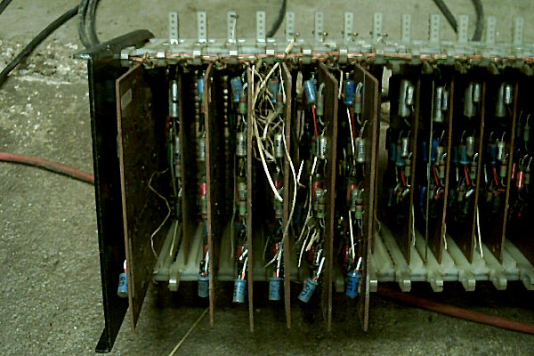
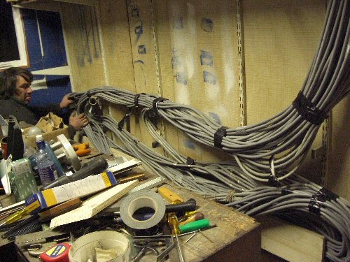
Here are Photo's from this major rework of Flossie's envioronment, this photo shows the Re-Routing of the Data Cables, to the decks.
Yes that is a lot of cables ....
90th Episode:- November / December 2008
Roger's logsArthur was finally moved out. This gave a great opportunity to improve Flossie, the working environment for us and I think, a huge improvement in the experience for visitors and the possibilities for photography. The remains of the old model railway which was being used as a shelf was removed.
All the spare PCB carriers which were stacked on top of the CPU were moved into the other part of the building where the bulk of Arthur had been stored. Much less claustrophobic.
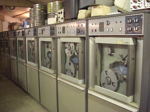
Decks A,B,C and D were moved from the end wall opposite the line printer to the side wall near the card punch. Decks E and F were moved next to them and then an unmarked deck and Arthur's Deck Y which had started to be stripped for spares even before Arthur left the Liverpool Victoria Friendly Society in the 1970s. We then had eight decks in a row, all of which are visible from the same angle as the printer, console and card reader. There were sufficient data cables for all eight decks, some were a bit too long, some a lot too long. All these had to be re-routed and the excess lost without being coiled up. For each deck there had five 37 core cables about 80 feet long, there were eight decks, so there were 5 x 37 x 80 x 8 feet of individually insulated wires inside the outer covers, about 23 miles, enough to reach across the English channel. I would estimate they weight about a third of a ton in total.
When Flossie was installed at Senate House, University of London, the cabling was overhead and entered Flossie through the top cover, and the hole is still there. The cables were attached to the backs of the tape decks with some excess to enable any deck to be pulled forwards for maintenance. The cable were run along the top of a step in the wall and held in place by pieces of steel bar. A trough was constructed from Flossie over a walkway to a roof truss and along this, over the doorway and boxed in next to the door. The plug end of the cables were put through Flossie's top cover with enough just enough slack that any set of cables could be plugged into any set of sockets to enable fault finding of decks, cable sets and 1301 electronics independently. The cables were laid into the trough and through the box (the box cover had not been fitted yet). Excess cabling was held up by specially made supports from Spur shelf uprights so that the cables zig-zagged without being kinked, coiled or rubbed on any sharp edges. A large plywood box about 30 inches high by 10 feet long and four inches deep was built around it.
Some multi drawer shelf units and shelves were bought and much work was done erecting them and rearranging spares into those drawers and onto shelves. In moving Arthur, many vinyl floor tiles had come unglued. Some of them were glued back and an electric polisher used to clean off (most of) the trails of plastic left by the decomposed tyres of the castors of the magnetic tape decks.
The line printer's paper trolley was put back in its rightful place and plugged in.
The card punch was to be moved from behind the power stabiliser to the front. The problem was the gap was too small, so the covers were stripped off. Still not enough room. The heavy power stabiliser rack was held six inches up in the air whilst the punch and its cables were manoeuvred underneath. Done on my own using some large wooden levers trying not to put my hands under the rack.
89th Episode:-September/October 2008
A dehumidifier was bought and will be kept running 24/7.
Flossie (ICT 1301 serial number 6) has for many years shared the barn with Arthur (ICT 1301 serial number 75 with parts of number 159). Arthur has been stored in parts, partly at the far end of the building, and part stacked around Flossie. There was a possibility of Arthur going to the Science Museum in South Kensington but in September hopes of this possibility finally were dashed. Arthur was not now going there, but was still going to move out of their shared barn, you might call it a divorce. Just like a divorce it was difficult to work out what belonged to who. The major units were easy but it was the smaller items which were difficult. Due to lack of space, Flossie had never been fully assembled. Before I brought her to the farm when Flossie was in Surbiton, she had 6 tape drives and 3 drums. Up to this time I had only connected up 4 tape drives and 2 drums. There were also covers, kick plates and top covers which had never been fitted to Flossie. There were also spare parts which were staying with Flossie for a while at least. So the separation was quite complicated.
In preparation for the move, Arthur's card punch was moved to the wall opposite Flossie's card reader and two tape decks were brought in front of the Flossie's line printer. Flossie's punch was mover towards the back of the machine (I just hope I haven't damaged any wires) so that we had sufficient space to extract Arthur's units.
As Flossie has been using Arthur's nameplate (which has the newer ICL name in ICL colours) for many years, a new one was ordered for Flossie, using a picture of Flossie's original one which has the older ICT logo in ICT colours. The new nameplate is a very good copy of the original, it has a slightly thicker frame which I can mill down in due course as well as adding a black spacer behind the aluminium plate which says 1301 so that it appears to float in front of the back board.
Arthur's mag tape control electronics were bolted together so we could identify and bolt on the top covers, doors, end covers, kick plates, corner cover strips, junctions, spacers etc. Then we knew that bays 13 to 22, the tape junction and tape power supply were all complete. The far end was then stripped down, leaving the Data Transfer Units (DTU) intact. We then bolted on the core store, drum electronics and drum to the DTU and did a similar exercise before moving on to the central processor racks and finally the console, printer, reader and punch. I kept finding bits of welded metal I'd forgotten about and spent a while figuring where they fitted into the giant 3D jig-saw.
88th Episode:- July & August 2008
The problem with one track of the paper tape reader not working reliably came back. The problem appeared to be with one of
the multi turn potentiometers in the read head. There are nine of these, eight for the data tracks and one for the
sprocket track. Four of these are of a different type, must have been repaired prior to me acquiring Flossie.
These are not only made by a different manufacturer, they also have a different resistance. They are long narrow items with a tiny adjusting screw in the end and two holes in them which need to be in the right place so that they can be mounted next to each other with a piece of screwed rod through them. I expected to have to adapt the mechanical design in some way to accept a modern equivalent, but on consulting the RS Components catalogue I found one which was not only the right resistance but also the right general shape with a similar screw adjustment. The spacing of the holes was not specified but it was as close as I was going to get. When it arrived and we compared it, it was perfect. Only the terminals were not in line with the originals, but wires bend so not problem. After Rod fitted this and adjusted the screw whilst reading a loop of tape containing alternately hex 55 and hex AA, the reader worked reliably once more.
At last we could get back to the interface we were building. Since the end of 2007 we had rebuilt it (now the Mk 3) with all the integrated circuits in wire wrap sockets and even the transistors in sockets for ease of modification. In the part of Flossie we were connecting to there is a connector which has various signals, the most important ones being Flossie's 1MHz clock and a signal to indicate an I/O transfer is in progress. This is true for 12 clock pulses, during which the B register shifts 12 digits to the right. Output data to the interface shifts out the right most digit (four bits) and it is also possible for input data to be clocked in to the left most digit, though we are not attempting this. The main problem was that after buffering the selection signal through a transistor it was not true for 12 clocks. The start of the signal was not clean enough. We battled with this for a while, tried chokes and got nowhere. We checked where the signal originated and it was fine. We unplugged the interconnecting cable so we could check the actual (buffered in Flossie) signal coming out. It was fine. We found that with the cable plugged in, even with the far end disconnected, the start of the signal was smoothed off. Time for a rethink and we considered various options. We decided that in 2009 we would build a board (the Mk4 interface) which would connect in place of the paper tape punch controller, which is a more modern (1970s) lashed up TTL board. If it works for the punch, it will work for a more general parallel interface made of TTL. It will not be as fast as the Mk3 was intended to be but it will work, though it might mean that the magnetic tape drives will have to start and stop, something we were trying to avoid doing in case the old frail tapes get stretched or broken.
I got my hands on a rack of proper punched card trays, the older type with wire handles. These came from a vehicle coach works which was closing down. Thanks to my niece Debbie who recognised what were using as storage racks and bought them for me. I also got some later type drawers from my old friend Richard Toft who had been using them for storage of parts for the full size Savage steam lorry he is building. All of the ready punched cards were then put in the steel trays. There are still new cards in cardboard boxes but of course these are less precious.
The identifiable card decks, comprising about 80,000 punched cards (excluding duplicates) were then sorted by their ICT subroutine/program designation ready to be read and made available on the Internet. I also annotated a file containing a list of items in ICT's subroutine library with what cards I have got. Hopefully the missing items will be found on magnetic tape in due course. There are a few hundred 160 column cards but if these are ever needed they will have to be read by hand or on a photo scanner and some custom software.
87th Episode:- 13/07/08
There is nowhere to hide for today like it or not it is the" Link to the 2008 Open Day Page "
Thanks to Stuart Fyfe, Morgan, Andy, Steve and all who showed up to support us on the day
including some of the original engineers, always a real pleasure to meet up and talk over old times.
hard to say how many people visited but estimated at over 200
mostly very complimentary and some interesting entries in the comment book
86th Episode:- 09/07/08
After a lot of work the machine was prepared today for the open day, a few last minute panic's as we discovered that some covers did not fit on the Paper Tape Reader. Final excercise was to run the Demo program and although we ran ok! we are planning a fallback if all fails.85th Episode:- 02/07/08
Still in prepare mode today, jobs completed = Tidy up Store unit ( Barndoor 4 ), We also removed and resoldered the control board for Deck D as the solder around the Valvebases to the actuators has lost conntact, probably due to a lot of movement as vavles were changed in the last 45 years. Last item was to add a diode to the 380002 ( read a card command ) and connect it to the 380007 ( Reject a card ) this is to overcome the problems we have with the card stacking mechanism, we are currently routing all cards read into the reject stacker, as a safety move !84th Episode:- 25/06/08
Today its a tidy up and test day. Roger had obtained new transformers for the paper tape reader Clutch and Brake supply, and fitted them to the PSU frame. It was ( smoke tested ) I will rephrase that! Powered up cautiously. and the unit worked well. No sign of overheating, however now we need to find the cause of data bits bieng gained from the tape reader head. A general cleanup of the photo sensor area gave us more reliability, and a reseat of the plug connecting to read head, seemed to cure the gained bit problems.Bouyed up with this progress, the latest version of the demo was loaded and transfered to drum at address 680. Whilst doing this we also backed up the short bootstrap to address 700 on the Drum. A run of this version started well and the machine is performing as it did during its working life. We were obviously feeling too smug, because at that point, Flossie blew a store access PCB, Digit 9 Bit 1 in Barndoor 4. We changed it and then felt very silly as the problem still existed, Why ?? becase we had changed the board in Barndoor 3 not 4.
OOoopppsss!
After that we started again and slowly rebuilt the loading of the devices the machine was driving, and we only needed a small revision to the demo software before we felt that it was ready for the OPEN day. Last action of the day was to adjust the read head now it seemed to have settled down ( Note the setting potentiometer for the track that was gaining earlier seems very Sensitive )
83rd Episode:- 04/06/08
Today all ( or most ) of our problems are with the Paper Tape Reader. We need this unit to load the demo Software and the Main Clutch and Brake Power supply is overheating a transformer. Is the unit pulling too much power or is the transformer failing? We ran the transformer with the load removed and it still started to cook !Looks like a new transformer is required, So after a little more work fixing up a rewind problem with Deck C, we settled down to try to hand key the demo software into the machine, It was a race as the room temperature was rising and eventually it was written to Drum and the machine powered down before it got too hot!
82nd Episode:- 21/05/08
" Ever had one of those days ? "It starts with the french causing a closing down of sections of the M20 due to industrial action on the other side of the channel, then just gets worse.
However in our darkest moments, our spirits were lifted as our efforts today were graced by a Visit from Tilly Blyth who came to visit our project and see what we have been up to. Sorry Flossie was not up to running a full demo for you Tilly, we now think we cooked something when the machine got hot at the end of our 14th May session. So its all hands to the pumps to fix the machine for the open day on Sunday 13th July 2008. At least we have a good demo program now thanks to Roger's hard work over the weekend.
81st Episode:- 14/05/08
Before we started work today we took the time to check out the power supplies around the store ands CPU area. These have not been checked since 2008 switch on, so it was no suprise that both the -6.3 and the +12.6 supplies were both out of specification. It was hoped that this would resolve our problems with the new demo prog, which seemed to be corrupting the main store, but only when tape reads were bieng undertaken.To prove the main store reliability a small program was hand keyed to put a data word into location 50 and move it up the store ( word by word ) to location 1850, this last location was then compared to the original word 50 so when it failed we knew we had a problem.
This proved to be a single core in a single address, something we need to fix, but its a big job so we limited our program to location 1050 and now the test runs without failure. There had been a suspicion that the store was suffering from address problems in every tenth word, Roger had even tried to program around the glitch by jumping over every tenth word in the new Demo Prog.
Now we could focus on the updating of the demonstration program used to show the machine to the public. Roger had done a rewrite to make it more flexible, some progress till Flossie got too hot then we had to close her down.
80 Episode:- 08/05/08
Work today continued on deck B, and it was decided a new relay was required. After much head and hair scrathing( and I do not have a lot to spare )
A new relay was found ( literaly ). The deck may be non standard but it now works , well mostly ! Work moved onto the card reader, and after much logic bashing even that joined in and started to work!
Progress of sorts is always welcome !
We celerbated by mapping what we had stored on the Drum and found a prototype of the Demo program, all good news !
79h Episode:- 30/04/08
Work today focused on Deck B, the unit has had problems for a long while, but it is one of the best and most reliable decks we have ( when it works ). The problem led to a need to pull the deck forward and I dropped from the top of the deck, into the space behind the deck to remove a service cover to access a relay from the back of the unit. When this had been done it was discovered that the deck had been rewired!The relay had been removed from the circuit and the unit rewired to an additional relay which could be accessed from the front of the deck ( Uuuugggg ! )
So not a lot of progress today, apart from testing the main store which had taken place whilst I was getting very dirty and dusty chasing relays !
78h Episode:- 7/04/08
With crossed fingers and a close eye on the thermometer Flossie was powered up today, the machine does have problems. But after about 25 mins most of thr lady joined in, apart from a problem with carrys in the Mill. Now Flossie is a mature lady and does basic arithmetic in Decimal, Sterling and now Binary But the difference between all of them is controlled by ' Fillers ' . When Flossie adds 1 to 9 the answer is 10 but to get the carry to the next hexadecimal digit she adds 6 to the total, that is the Filler value she uses for Decimal working. But Flossie had big problems with this, eventually we found a duff gate package which was replaced and now all is working ok. The day closed with a working CPU and all of the main store running ( work over the years is showing and this machine is getting more reliable, visit by visit.Start of work in 2008
77th Episode:- 25/09/07
I arrived to find that we were having another window replaced, nice to know the air condition is bieng maintained ( read the earlier diaries to get the joke )Our problem from the last episode returned today, so many hours went into discovering that the real problem was a failure of the 68 ( compare ) function. This was chased down to the board in position 6E14, which was on a temporary connector ( a rubber block that pushes the pins together ), fitting the board properly with wrapping wires cured our problem.
We could now move on to the implementation of the interface we need to recover the software from this machine. Various problems were resolved by us changing the logic and tweaking the timing on the interface, eventually we discovered a blown transistor on the board which stopped any further work.
As an aside we have expeienced a few problems with this interface, the earthing is a problem as the logic on flossie is Zero volts to minus 6.3 volts, and the interface is standard TTL, using zero volts to plus 5 volts. By floating the interface at minus 5 volts to the true earth we seem to get the signals balanced, but the minus 1.3 volts difference does give us problems. The earth connections we use are massive when you consider the signals are only about 2 milliamps max current. The transistors are used to cut off this negative swing which TTL cannot tolerate.
I will create a page to explain this interface soon, but getting it working ASAP is our priority at present.
76th Episode:- 12/09/07
The first item today was to keep our store fully functional, and we needed to replace the A7 board in Digit1,Bit2 which had failed since our last episode. We now seem to be having some problems with either the 66 ( increment Function ) or the 28 ( preindex ) function. We worked on this problem, but the symptoms were very intermittent. We were sure that at one point we saw a 66 funtion fail to increment properly. But after reloading the code from drum it seemed to work flawlessly ! The day ended with us feeling a lot more confident with the state of the machine after all the years of work which we have put into it !75th Episode:- 29/08/07
Well today finds us continuing with the work on flossie's memory, for several weeks we have been trying to get the last store module, barn door 4, fully working.First however Roger showed me a new rack that now holds a lot of the boards we have changed over the years. These need repair and we must find some time this winter to put some effort into bench repair of these boards.
So far we have progressed to a point where store module 4 is now basicaly functinal, but with many problems left, we have about 85 percent of this last module working. Fixing this means that for the first time since the project started back in 2003, we now have the possibility of a fully working store and the window on the last phase of our current project opens to allow us to start capturing the software stored on the magnetic tapes.
First problem is a lot of groups of ten addresses which are not functioning so we changed the G6 board in barn door 4 for addrssses 80/180 but to no avail. Digging deeper into the logic we tried the G3 decoder board in 10G20, but the problem persisted. After a lot of head scratching we found another decoder board in 10G22 which seemed to have an input but no output.
Yes! we now have a lot more store working! But we were left with two individual addreses which looked very bad, 118 and 146. Due to the age of this machine a lot of the ' Spare Cores ' have been utilised. These are lines that were built into the Core Stacks, now over 45 years ago, and are used by ' jumpering ' the spare lines into use.
Our approach is to change any external components when we can, as these are current stearing diodes for each of the two thousand words of store. Further both of the defective words were already swopped to 'Spare' lines. After a little more work we had all the 400 words of the module working. This is the first time this module has worked since the project started over five years ago.
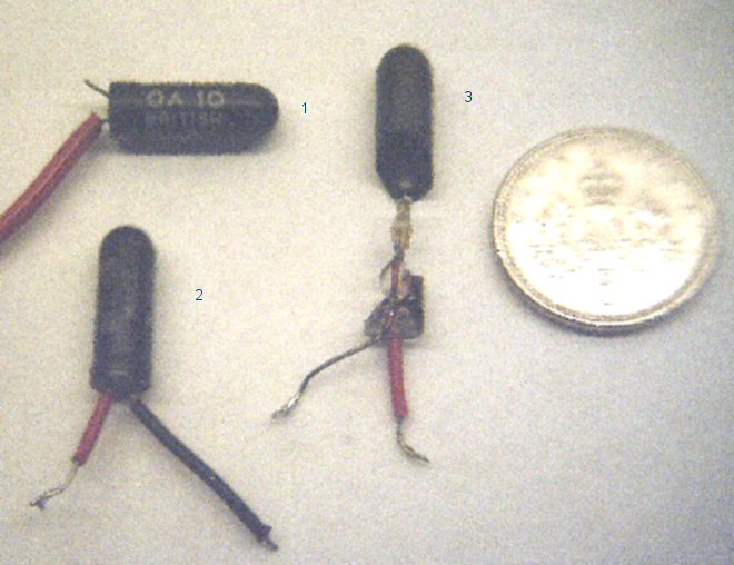
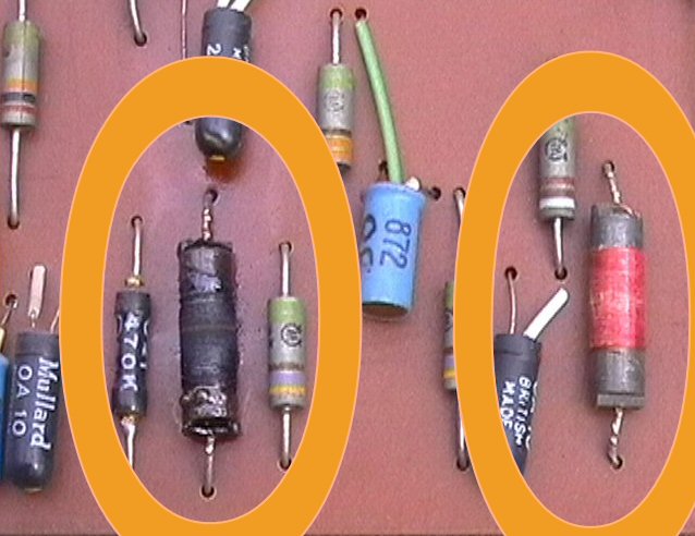
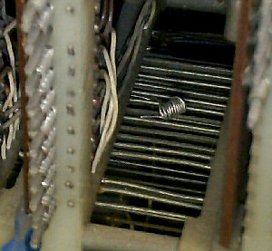
A quick photo of the type of diodes used in the store modules on this machine, Mullard type OA10
key to items
No1 is a diode that has been 'cropped' out to allow a replacment,
No2 is a standard replacement part, second hand of course !
No3 is the type of failure which can occur after over 45 years's, the glass shell has ruptured
and the junction has been exposed to moisture which has degraded the alloy.
The 5 pence coin on the right of the image is for size reference.
For your information:- the whole 5 store modules use at least four thousand of these diodes for stearing the current to where it is needed !
Now we had just one single word in store module 2 which was failing, this has been repaired a few times before. We had changed the current stearing dioes, so were now faced with moving this word to one of our precious spare words. As this was the last problem that stood between us and a fully working store, we had little option but to sacifice another spare, so we jumpered in the spare line in the core plane.
Now we expected a fully working store, and indeed the word did now work and store data, but one bit was now failing Digit 8 Bit 8.
This presented us with another dilema, we had to choose beween rewiring a whole column of 400 cores to the last remaining spare in the module, or consider untried options as we could just crosswire the one failing core plane into an abandoned column which had 40 or 80 words which ' may just be ok ' ?
As we have on old ' Core Stack ' on the bench we were able to check out the the idea. Although it did seem somewhat of a whacky idea, we tried it !
Now even this problem was solved !
But just to prove that flossie does not give up easily, the just repaired store module four developed a new fault, word 140 failed !
After our experiences over the last four visits this was easy to fix by swapping out the failed diode. I also took the chance to tidy up some of the earlier work from previous visits, and our crocodile clip fix from the previous episode was replaced with a properly wired connection.
Now ' AT LAST ' we had a store of two thousand words by 48 bits wide working again ! A milestore event in our five year old project.
A store test was coded up to test the store to ensure we had no lingering problems ( or doubts in our own minds ) the test ran for over an hour whilst we exercised an elderly apple 2 computer from about 1984, as old as this home computer was, Flossie is over twenty years older !
The day ended with us agreeing that we had today passed the 90 percent mark in our journey on this project.
74th Episode:- 14/08/07
Work continues on the defective store module ' barn door 4 ' . This has been physicaly disconnected from the machine power lines in the past as it has blown fuses in the store power supply and pulled the whole machine down! The first thing we noticed was that by comparing the signals on module 4 to the signals on module 2, there were considerable differences. Something was still stealing current from the rest of the module and when ever we addressed the one working word then all the signals looked good. We reduced the problem to a small diagram of the lines of wire running through the core store and the diodes which stear the current to the correct wire when addressed. A lot of time was spent discussing the possibilities, and the only thing which fitted the problem was the fact that a diode had gone short circuit ! but how to prove it ? it was after all ' one diode ' in 800 or more that the module used to address the store.The store module boards recieve logic signals from the machine and convert them to Current levels to either switch or not switch magnetic cores. This means that with the boards connected there will be quite large back circuits if you just meter the core array for resistance. However if we could pull or disconnect the most suspect boards then a meter test would show the problem. So with meter in hand and the 'Suspect' address lines boards disconnected a trip down the 400 individual address lines was started, almost down to the last two stacks out of ten a possible short circuit was found. Eureka !
Now the problem was to convince myself that this was indeed the problem we were looking for! Some considerable time was spent on the bench with our example core stack. A plan was formulated that if I removed two more boards then the possibility of any back circuit was removed. This was done and the short circuit still existed on the store module, but not on the bench reference stack. As this was a diode that had gone short circuit another diode was added in series with the suspect diode and the current robbing problem was solved. Unfortunatley the wiring around the stack was now bieng disturbed and a critical connection wire fell off at this point. A quick link with a crocodile clip cable restored the connection, and allowed testing to continue. We actually have over 70 percent of this store module working now, and just a small celebration was called for.
We have run out of time today but this store module is now showing signs of real life now and all of the work that has gone into it is paying off !
73rd Episode:- 01/08/07
This is the first day after our open day and a lot of time was spent tidying up and clearing the decks for work to continue on the real project. But before we consign the 2007 open day to history we do seem to have made a small quantity of money from our visitor's and Flossie now has enough money in the bank to fund her power for about 300 hours.Many thanks to all who visited us on the open day in 2007 and donated towards this project!
A general test of the state of the machine was done and although flossie did get quite hot on the day we seem to have survived with no new problems.
To restart the work the Defective Store Module No 4 was reconnected, and to prove a point blew the store power supply fuse immediatly !
We disconnected the five power wires which deliver the 22.6 volts feed, and reconnected one at a time after repairing the power supply again. The original problem of the store pulling power relative to the number of bits in the data register still exists.
Word 1167 still playing up in store module 3, so we replaced the stearing diodes again ! Why do they keep failing ?
So now we are left with 4 out of the 5 store modules working ! It is time to reconnect the failing module No 4 and find the power problem that has been around for far too long.
After reconnection we checked the voltage at the power supply and as this supply is tracked by a thermsistor to compensate for temperature, some time was spent ensuring that the supply tracked the correct graph according to the manual. Although we proved this was correct, whilst we waited for the load and temperature to change we ran a simple test of the module and whilst testing all the address lines going into the store, we were very lucky and found a major current source in the read and write logic that was stuck at a half level. It was neither on or off but stuck at a half level. It took two stabs to find the problem but the control board which feeds current to the individual address lines, was found to be defective. Now at last we had found the fault which has plagued the repair of this store module, and blown fuses many times in the past.
A reassesment of the situation however showed that we had many other problems with the store module, of the 400 words only one word seemed to work and all others only worked if the number of bits in the word was limited. In summary the current needed to switch the Cores was biend robbed somewhere!
But at least one word did work and that was better tnan a store that had refused to work at all and blown fuses.
72nd Episode:- 15/07/07
" Link to the 2007 Open Day Page "
Thanks to Stuart Fyfe and Morgan ( and very Nice to see you Olwen ! )
hard to say how many people visited but estimated at over 240
mostly very complimentary and some interesting entries in the comment book
71st Episode:- 11/07/07
Open day prepare = dress up flossie and setup lights/facilitiesA lot of time today was spent tidying up after our long fault finding sessions on the store. Many boards needed to be re-wrapped and conneted properly, as the use of 'tempory' rubber connectors to make a test connection can give more problems than they solve if they are not made good afterwards.
70th Episode:- 04/07/07
Work today focused on the coding for a demonstration program for the open day !The resultant code is stored on drum bands
640 and 860 :- load 810000-200xxx-004000 to run
24 = peri activity
21 = sprag paper feeds
All devices mt2,3,4,pt,cr,cp,lp
69th Episode:- 20/6/07
Roger had worked on the store over the weekend and it had blown the power supply fuse again, we decided to isolate the store unit again, as it may stop the machine on the open day. But before we did that, we have noticed that this store unit has a unique fault. The power surges can be intitiated by just presenting data to the store, we do not even have to write or read the data. Solve this problem and we may be able to fix this last store problem. We do have about 1,200 words of store for the open day demonstrations, and that will surfice.On to the CPU problem, the code which we used last week was still on the drum and the problem seems unchanged, now we could start working on it. A lot of time was needed before we started to suspect the control register update mechanism, this works perfectly until an instruction which uses steps 21 or more is issued then strange things happen in the control registers.
The area around the CR update was scoped, and we could prove more than one update was happening, but only after a long function ( What a Beastly Fault ).
Just to complicate things the machine never fails on manual control, this is a problem which only fails at full speed.
Now Flossie only uses the minimum time to complete any function, some intructions will stop after 12 steps and others take a little longer if they need to write results to store. Termination of functions shorer than the full length cause a reset to be sent to the timing chain, and the timer starts again on the next function. A lot of work was done to prove to ourselves that not only were we getting more than one update per word, but we were also getting duplicated steps from the timing chain ( No wonder we have a problem !)
Continued work isolated a binary which was responsible for step 22, ( 6B11 ) now this should be cleared if a function which is only 21 steps long is issued. But as it was not clearing it was sending a second pulse back into the timer, whilst the next function was bieng obeyd. Resulting in chaos as the machine duplicated steps including updating the control registers, assigning carry bits in the Mill and moving data to and from store.
Much Celebration followed, as we now have a working machine for the open day ( and only three scant working days left to set it all up ).
68th Episode:- 12/6/07
Today was spent wrapping all the boards we swapped in the store on the last visit, about 18 boards in total, a chance was taken to service the hard working wrapping tools at the same time. After this session all of the five store units have all boards wrapped in.The last hour of today was spent on our CPU problems, and although there was no breakthrough a picture of the problem is beginning to show. The machine is jumping out of loops when a long instruction is obeyed, if the instruction is in the first half of a word it takess a long time to break. If the instruction is in the second half it breaks a lot quicker. Just what this means will have to wait till next week, but this at least is a way into this problem at last. I have saved the failing code on to the drum on band address 900, I hope its still there next week when we need it.
Sad news is that our new scope has stopped working, we need this to solve the CPU problem, so next week its the scope first and the computer after.
67th Episode:- 6/6/07
Attention moved on today to to the next store unit Barn door 4, this has had its power supply isolated, as it was blowing the store power supply fuse. A long list of failed baords later and the store unit was not fixed but at last started to give data back. So we can write to the store unit and " Sometimes" we get some of the data back. A lot of the board are on temporary or rubber connectors, a lot of work is needed to tidy this up.We have a new scope to use today it's a 4 trace HP 54501a and a fine tool it is too.
66th Episode:- 23/5/07
Back to the memory problem, the the machine mostly held up today, and we were able to add Barn Door 3 to our list of working memory. Its been a long wait but we now have 1,200 words of contiguous memory ! But it took 4 control boards and 2 data board before we had a fully working store unit.65th Episode:- 08/5/07
We started work on barn doors ( main memory ) only 3 of the store units ( Barn Doors )working out of 5.However we started to suffer from corruption in the control registers, it took a long while to identify the problem ! And any function which has to write away a result after a computation stands a chance of breaking the machine.
Just to complicate the issue the fault seemed to be temperature sensitive as well. It took all day and we are still unsure at the end if we fixed this problem or not !
64th Episode:- 10/4/07
Today we have a new problem the machine seems to freeze when doing a multiply, intermittently ! The first try was to find what was causing the problem and we found that if a packed digit was in the B register then the machine might freeze. A lot of logic is used to decide what is the quickest way do the multiply. So a lot of gates were changed to allow us to find this fault, far too many, as our stock of spare boards is dwidling quickly.Eventually the right board was found and we can run any combination of digits and all now works well.
63rd Episode:- 28/3/07
The 28th of March saw the first visit of of the 2007 work on this project. Work on the mag tapes ( replacing duff lamps ) continued and after some considerable warming up flossie was powered on, ( always a thing we do with crossed fingers, after the hibination period ). Lots did work but, we had to tweak some of the ageing power supplies back to specification, and then we could work on the store problems, much head scratching untill we found a bit in the A register Digit 7 bit 1. Board replaced and now we can talk to as much store as we have working, just 3 out of 5 units to date.We are left with problems with the micro order steps which are stopping the multiply and the drum functions woking, however the investment in time on the Tape control unit has paid dividends. As everything we fixed last year still works, so we only have the write commands to fix and we may be close to all the electronic systems working.
Now the good news *** The Open Day in 2007 will go ahead *** !
Start of work in 2007
2006 Overview.
Well I do wonder what I will return to in 2007, Roger has done a lot of things this year including
fitting a new roof covering, a new window and some of the old ventilator shafts are now bieng taken
out and covered over in the roof space, as they did leak when the rain was heavy ! At least
I am happy that the work we have put into this project so far ( slightly over four years ) will be
safe over winter.
There are plans for this machine's environment but like me, you will just have to wait and see what
happens. I certainly plan to continue and as soon as the weather allows, I will be back to start
the proccess of extracting all that software from this machine.
For all of those who have followed our task over the years ! Thanks !
Next year could see the harvesting of the software we have worked for.
It could also be the start of a brand new project. ;o)
So as they say ! Watch this space !
End of work in 2006
62nd Episode:- 13/12/06
This is the latest date we have worked in any year and the temperature is still on our side. This is the 1301XOUT " last try for 2006 " although we can now connect to the interface and set test conditions, we are experiencing a lot of difficulty getting the decode to work. After a lot of work today we discovered that the levels on the interface are not stable during the length of the 1301 instruction. The control register is moving and changing the levels we are trying to decode.So now we have to resolve this issue, we can either modify the interface or put statisicers on the new 1301XOUT board. So its time to put the covers on Flossie for this year !
61st Episode:- 22/11/06
Testing of the 1301XOUT board could only start after we had cabled the unit up, the first problem was the clock driver from the interface. An add-hoc design which matched the impedence of a standard clock loading was tinkered together, this improved the overall situation. After more work I discovered that I had failed to allow for the inclusion of input resistors to the board from the 1301, we were over driving and perhaps blowing up the transistors which are there to give us clipping and isolation from the difference of the minus 6.3volts and the minus 5volts of the TTL on the board.
60th Episode:- 08/11/06
Repair IAS, address decode problems, and address 788 single word failed, this last item proved to a defective diode which was replaced.Then arrange the best configuration of IAS, it looks as if the best we can get is words 600 through to 1800 about 1200 consecutive words. SO as such Roger will be producing the software to run in this configuration.
Next week we will try to connect the transfer interface which is called the 1310XOUT ( as in Transfer OUT ). It is designed to take 12 digits, by four bits each of data, and throw it into a FIFO, then allow a PC to transfer six by eight bits of data out and file it, transfer speed is going to be important but to start with lets just get it working !
59th Episode:- 15/10/06
We started with a dead Scope, it proved to be a duff filter element, so we just jumpered the connection out !Long slog today, and we can actually Write to a tape, but only sometimes ! Looks like a timimg problem still has us beaten.
58th Episode:- 11/10/06
Most of today was spent decoding how the machine reads tapes in all tracks format ! "WHY" because we may need to read the tapes ourselves. By knowing all the parity bits as well as the data bits we can reconstruct partial failures, the machine can correct single bit errors but multiple errors will need some more computing power to resolve. Although it was a lot of work today, we are confident that all known single bit failures can now be found and that a lot of multiple failures will also be correctable.57th Episode:- 27/09/06
First off today, the good news ! we can still read magnetic tapes !But picking up from where we left off, we cannot write to any deck, the tape does not move and the DTU write control freezes, in a startup stare called "Prepare to Write".
Logic tracking followed, as we worked our way through the multiple interfaces to the tape decks, the address selection logic and the cables and boards to and from the DTU. ( The engineering term is Logic Bashing, moving from pin to pin checking logic levels ).
We then moved to head bashing, as we could not understand why a simple gate would not work. It had only three inputs and they were all moving, eventualy Roger spotted the fact that two input's were complimentary, when one turned on the other turned off so no output, the reason was no write ring on the tape. Ok so now we get an output and trotting all over the DTU we eventualy found 19H7 pin 6 no output we replaced the A4 package and now we get the tape deck's to move. However the DTU locks up in a different state, this time its "Interhead gap". This could be good news as you enter this state to allow the Write order to terminate by giving the freshly written tape a chance to make it to the read head for checking. But you also go this way if the order has failed, so it can complete and report errors.
Ok enough is enough! we checked we could still read tapes ok ! and the battle continues next week.
56th Episode:- 13/09/06 = (In which electronic hiccups lead to a miraculus cure for magnetic malladies.)
Today starts with us still only 66% complete on Aim one our project. But from square one we had distractions. Roger had emailed to say that on Sunday he had tried to work on our problems only to be stopped by a smell of burning, he had wisely turned the machine off until today !
The nose confirmed that indeed something had gone up in smoke, but what ? A tour of the machine could not confirm a sepcific area of concern ( smell ). So power was applied and and still no smoke, motors were turned on and off and not a trace of the smoke was produced.
Eventually we left the machine on and running whilst a repair to Tape deck "B" was completed and a pinch roller was replaced, still no smoke!
So onwards into the DTU problems, the approach was to compare the two half words both the working six digits and the non working six digits and we hit pay dirt almost straight away, the signals were different.
We had found a Duff G1 package and replaced it, but still the same fault! We also swapped the single G2 input and even isolated the A1 package in the signal path,, and still no joy. But the differnces in the two signals said it just had to be the cause of our problem, much head scrathing and scoping followed. In the middle of which the Control Register Selector Switch knob fell off in Rogers hand, but it was over 40 years old, and had lasted well. And then the Hiccups started.
A test would only run for a short time and " Blam " all kinds of errors were brought up, Slip Pulse, Drum error, IAS error's . It was impossible to fault find as every 30 seconds or so the machine would lock. some time was spent on the Power Supplies and checking the tape supplies in paticular ( thoughts of that burning smell uppermost in our mind ) . Eventually we just sat and timed the glitches, Flossie was hiccuping every 35 seconds or so, but why such a regular time interval ? After some thought Roger went to an adjacemt garage area and turned off a battery charger, the result was Hiccups cured.
Now we could continue with our problem and still spent a long time before we realised that the replacement G1 package had the same fault as the original one. A third G1 package cured the fault, Boy Oh Boy, but it was nice to see the back of that problem.
One major problem down and the next hove into view, the word shortening problem was still around, however we are now wise as to what causes this, and a careful setup of the minus 6.3 volts in the tape bays resulted in us seeing the problem go away ( we know there is a suspect board in here somewhere but it is going to be a long while before we can run test software with differing block sizes and content to find it ).
Now we can read tape 288's label without any corruption, so what do we get to prove it ? "UPDATE" is now decoded as "SORTEDUPDATE" all twelve digits ok ! A quick read of another tape's label gave us "MEM_MAIN_FLE" again all twelve digits ok, throwing caution to the wind a few blocks further down the same tape we scanned a data block and found another field with "LONDON_VILLA" which seemed a little odd but pleased us, then we read the next two words and continued decoding and got " GE" making the whole thing "LONDON_VILLAGE". Well after a lot of work we can read some tapes on some deck's and the final Aim of the project is now achievable.
We decided it was not time to go and get drunk yet! as the day was almost over, but we could not resist the temptation to try a write order now we could read data. This promptly failed, the Write control locked awaiting a deck to move and nothing did, so we have another big problem with write but now we have the read chain to fault find the write chain with, " And that is for another day ".
But today closed with us revising our progress from 66% to 78% which is quite a jump !
55th Episode:- 30/08/06
We started today knowing that we had all of the problems outstanding from last week, the big issue was did the situation remain stable or was it getting worse. We would only know when we powered up! so after checking the temperature carefully and crossing our fingers, the power was applied. it took a little while to re-assure ourselves that the situation was unchanged. We are still getting a form of data corruption where the individual data words are bieng shortened and we think we can still see the old problem of left and right data duplication under this new problem.
A lot of today was spent running round all those busy little counters in the DTU, whilst a tape was read block by block, we used this tape most of the day till the deck showed signs of wear. The pinch roller started to loose its Neoprene coating, still not bad after over 25 years, this deck will need some TLC next visit.
Again after a while we had proved that the only thing we could find was a duff board in position 17K6, however changing the board did not provide a cure to our problems. So we started checking all the timings of major signals around the read path and even proved to ourselves that the original duplicated data problem still existed. Only then did we start on the basic's and a check of the voltage's in the DTU showed the minus 6.3 volts to be about 6.02 ( about five percent low ). Checking the voltage at the DTU power supply unit showed both supplies at a healthy 6.35 volts, so where was our five percent going? A crawl along the wiring and power distribution showed nothing amiss, although a few spiders were chased away from thier well established homes. Eventually we got back to the far end of the DTU and to our surprise the 6.3 volts was now 6.29 ( we had obviously moved a bad connection in the wiring and made it good again )
Now most of our data was good again, we just had our data duplication problem back, but the words of data are full length, and we closed the day be decoding once again the 6 digits from our reference tape No 288, and were rewarded the magic of " UPDATE " again.
In summary if we can only find what is causing this 6 digit duplication we may be able ( read errors permitting ) to start to recover the projects precious software locked away on the reels of tape. However the problem is defying a logical solution. The day closed with jokes about the kind of logic we were applying to the problem, perhaps if we started to apply some impossible solutions then we may be able to solve our impossible problem, but only time will tell.
54th Episode:- 16/08/06
This trip started with some work on an IBM keypunch, Ok I know its not Flossie but we will need to punch cards on something. The designer used BRISTOL Keys, which were always a little strange, they have flutes cut into a round key and matching heads on all the screws. But after much head scratching the unit was reassembled and when we powered up ( and pushed the modifed belt tensioner by hand ) the machine did indeed feed a card from its hopper, not much more than that but at least a sign of life.
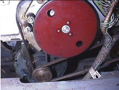
Now it was Flossies turn and from square one Flossie was not happy, the stable situation we had achived last week had gone, every attempt to read a tape block gave very differing results and there seemed no logic to what we were getting. So we worked around the DTU and proved several important points.
The transfers started ok from the Computer end, including updating the address in the DTU
Our best guess is that we are either failing the transfers because we are are timimg out or that a counter is faulty. So we checked the following ( the Digit pair, Data gap, Word and Read control counters ) all seemed to be running. We even managed to step the DTU with 3 pulses per second from the engineering panel, however suspicion stared to point to the " Read all tracks " switch located here, and Rogers switch cleaner proved it was playing up.
After a resolder job ( did I knock that wire off ? or was it loose ? ) we have a slight change in our fortunes. We seem not to get a full signal stating that the end of block had been detected ?. And what was a full word last week is now truncated to 2 sets of 3 digits in 1 to 3 and 7 to 9.
Now the DTU is composed of three major blocks, the Write Data path, it's Check Read path and the isolated Read Path. The plan is to resolve the problems with READ first, use the Read via an engineering facility to fault find the WRITE path and when we know we are writing good data fix the CHECK read part.
However to do this we are reliant on tapes written over 20 years ago, we are in a Chicken or the Egg situation and we do not have either, yet!.
We knew the DTU was not going to be easy to fix, and by golly gosh we are proving ourselves right!
53rd Episode:- 09/08/06
Ok this trip we mixed our work with the replacement of our Air Conditioning Plant.
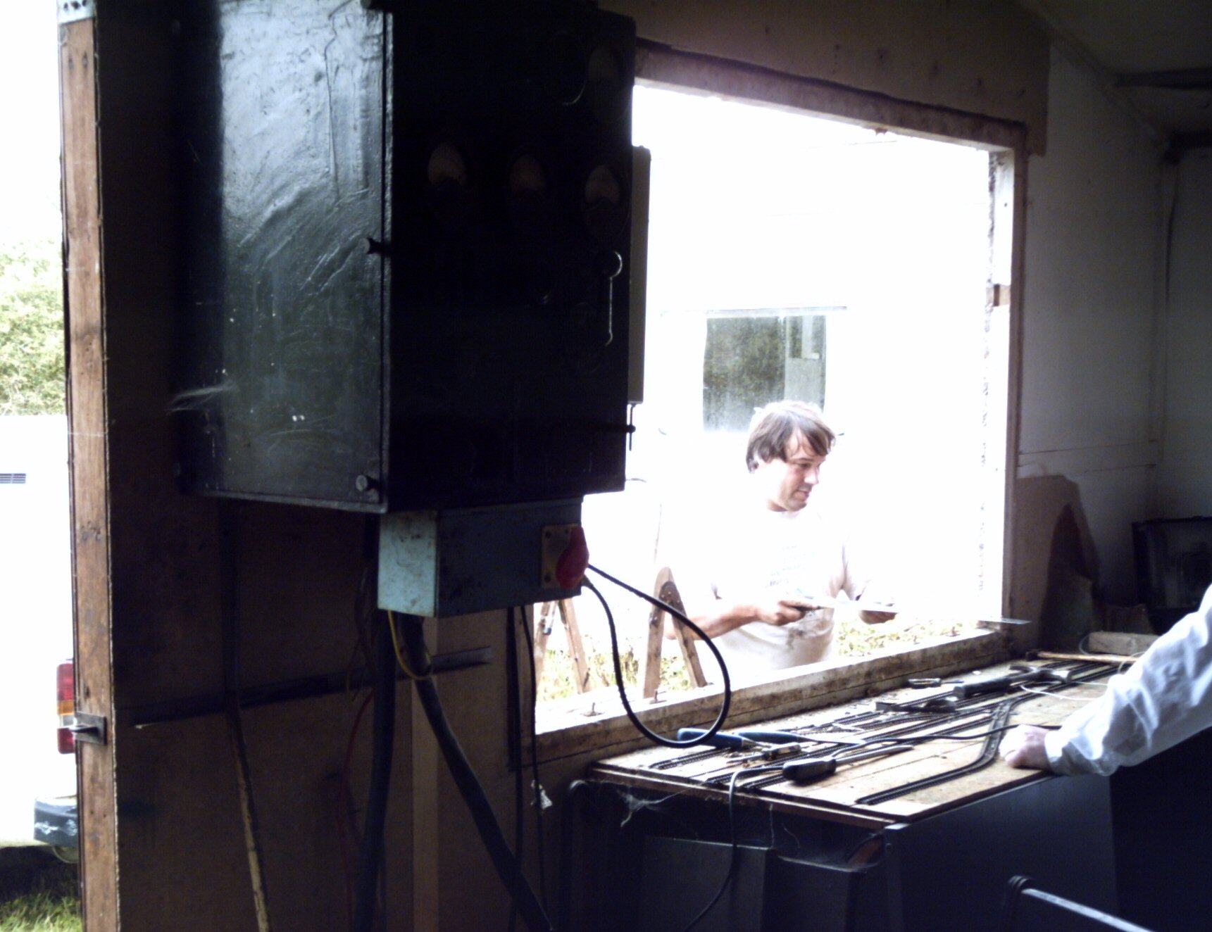
Yes that's a new window going in, how does it work ? well you open the window to cool the place down and close it to warm the place up, simple Huh ? But joking to one side, we needed this, the integrity of the building was at risk.
The first news was that we needed to fix up one of our Mag tape decks, giving us a total of three units for comparative testing. That done the initial results from our tests were very disheartening as we were getting different results to our last visit, and different results from test to test on the same day. An in depth investigation ( we looked at the enginering light's ) showed that the DTU was doing its own thing, from time to time. Randon spins of the DTU were taking place overwriting the main store before our very eye's. Suspicion deepened when the trail of evidence pointed to an addition to the DTU used to control the 1900 interface.
Then we started to suffer two new problems, first was that the drum system started to give " Slip Pulses " saying that the drum and machine was getting out of step. Whilst investigating this we started to get a new error saying that the store was suffering from errors.
After investigating and resolving a few duff boards on the way, ( 11G8, Part of the dreaded Q Counter, and 12A4, one of the main clock amplifiers with a very shortened output pulse width )we stood back from the problems and evaluated all the evidence. Was there a common thread to this? and indeed there was, after agreeing that we did not need the 1900 interface to get the basic DTU working. We isolated the line giving this signal, after five mins of error free running, and another five for good luck ! all of our problems had vanished. ( Phew ! ) See Episode 46 and 6 for more details.
A further attempt at testing produced not only stable results, but results that we could understand. After a dig through the magnetic tape convention's manual we could read header labels from tape's, the data was not only repeatable but half of each word was decipherable, and further the size was correct for a tape label. So what after all this time caught our attention, the combining of zone's and numeric's from just two half words gave us this six characters ' UPDATE ' the hand written sticky label on the reel of tape stated that the tape was a main file update.
So in summary we have recovered just six letters of a tape label, but the inference is massive. We can get the data back after over twenty years. Wish us luck, the 2006 part of this project is underway, and this discovery today means we can reach a major aim of the project.
52nd Episode:- 26/07/06
After a small incident which involved topping up the dashpots in the first Drum's overload trip. And it was no surprise to find that Roger had not only the correct oil, still in a sealed bottle, but the instructions as well. Work this visit continued as we tabulated the results of trying to read three reference tapes on differing tape decks. Only two decks were working this visit so some time was spent repairing a third deck. Results were somewhat confusing and we seem to be getting either extra data or corrupted data, however the results are repeatable from each tape and are the same from deck to deck. All we have to do in understand what we are getting in terms of what faults this means we have to fix, ( Simple huh ? ) well we hope so!
Although we are pinning our hopes on resolving our faults on the READ channel only, to start with, we did start to investigate the write chain. There are further problems here and we did fix a fault where the Write Control memory was not in a start state.( 19H5, pin24 ).
51st Episode:- 10/05/06
Work restarted and flossie was rather cold on this day, after running the fans for some time we still thought it was a little low on the temp side . So a slow switch on resulted, we ran the drum up and all seemed ok. we risked firing up the machine and we had some major problems with the main store ( IAS ), but by the time we had found two duff store data boards ( A7's ) and replaced them the temperature was back on track.
We were very surprised to find that we could load some simple programs from the Drum and although we got data error's, the code did run. Adding some mag tape decks by powering them up and and Flossie seemed to be much better this year, thanks to three years of TLC.
At this point we started to investigate the remaining major task, which to to fault find the Tape control unit or Data Transfer Unit (DTU). We do not have the correct tools for this job, all of our tapes are at least 20 years old and our start point has to be can we read any of these tapes at all.
Start of work in 2006
End of work in 2005
50th Episode:- 05/10/05
Work continued on the interface, trying to link an Apple Mac Laptop to the interface, but no joy. Well some you win and some you dont. Hey this my 50th trip, in three years work here, it must be time to review what we are doing and the general direction of this project, we are about 65 percent through at this point and Winter is fast approaching. Time to stand back and do a long review of progress to date !
So we will be in touch with all of our supporters, and post an end of year Summary soon. 2006 will be a different year for this project ( one way or the other ) . Just to prove flossie has her own view, at end of play this day we had to do a basic fix when after running all day the machine started corrupting the Control registers. A G1 package in 5B17 had gone duff, so one more vintage PCB joins the list of parts we offer to our supporters.
49th Episode:- 07/09/05
Time to work on the tape punch again, this time we found that some of the problems were still bad tracking and shorts on the board. We are winning, but very slowly on this item.
Big new item ! = We have built an interface to connect a PC ( laptop ) to the I/O connector. We seem to be able to send one 4 bit digit of data under PC control ( out of little acorns ) Add-hoc redesign for Roger means we were able to extend this to 8 bits.
48th Episode:- 24/08/05
We have recieved a delivery of blank paper tape and teletype rolls, so first job today is to replace the Paper Tape Punch interface driver card. This is a non standard part of the project, as a Paper Tape Punch on a 1301 was a seperate device, but this unit is an ad-hoc extension to the Paper Tape Reader Station.
It drives a teletype 100 char pert sec punch via some A28 ( 1301 standard ) cards and a prototype board made with Vero board and Vero wire. Unfortunatly in episode 39 we started to suffer from power supply problems in the paper tape station, the result was a damaged board.
Although rebuilt this board is proving very unreliable ( after all it is only a prototype )
The edge connections and pcb copnnectors are very poor and the vero wiring is now brittle with age and keeps breaking. If we cannot resolve this problem the only sensible action is to stop putting time, effort and money into rebuilding this board and make another with a good quality edge connector and real wire.
Thank god the effort put into resolving the Paper Tape Reader Power Supply problems has paid off in the form of a working paper tape reader !
It was proposed after episode 47 that we utilised the reader head connections to the second channel, to stream data into the machine via the installed P.T. bootstrap. To make this happen a small interface was built that allows a laptop to set the state of 8 data bits, we now tried to implement this idea!
The first blow to this plan was the fact that reader channel selection logic has been changed in flossie, in fact logic rack 2G is a complete rebuild. Unfortunately not to any existing standard in either 1301 software or hardware command set.
The rest of the day was spent on my knees trying to understand the 36 way connector that there seems to be little or no documented information on, Galdor added this I/O port but no recorded use of it exists in the documentation.
The first result of this painful exercise was that we think we know how the socket is wired, and by applying the signals from the laptop and interface we can see data getting into the "B" register. As this PC interface was designed to drive a paper tape interface, we need to revise the logic as the actual logic bieng driven is unknown and the drive levels seem to need a higher level than normal. However it may be a way into the machine, the big drawback is the lack of a loader for this route, it is a pity the tape reader route has been blocked, as we have a bootstrap for that route. The second result of this excersise is that I was late home trying to get this to work, and lost a floating 5volt PSU as it started to burn up either due to a short or the old floating -6.3volt which is a problem interfacing to flossie. The third result is that after working for over two hours on a socket only seven inches above the floor, in a dark and cramped area, my knees and back are telling me I should not be doing this at my age ! However we will try to document the connections we found in the next dairy entry.
47th Episode:- 10/08/05
After the open day we had a problem with a power supply in the paper tape reader, a sealed transformer has failed. Today a reworked PC power supply was fitted it now supplies the plus 12 volts line and seems to handle the current load. The voltage is a little low but useable!
We moved on to the problems Roger experienced with the paper tape reader gaining track 3 ( bit 4 ), after a strip down of the elliot reader head and making up paper tape loops with alternative one's and zero's punched. We traced the problem to a potentiometer in track 3's read amp, the wiper has a dead spot and this was giving noise, moving the wiper has settled it on a good part of the track and we are able to get a reliable setting.
A small period of time was spent on investigating Deck A, and after a little work the main mechanics of the deck are working, and the servo's are running, this is another contender to our stock of useable mag tape decks.
Flushed with this success we tried reloading Initial Orders onto the reserved bands of the Drum. This involved reading paper tapes into flossie and then manually patching the code in store to incorporate the paper tape bootstrap code !
The patched code was then written to the reserved bands on Drum One, a quick test showed we had a working set of I/O's . An engineer's format punched card was placed in the card reader and all five store locations had the correct code in store when it was read. We did notice that a zone and numeric component had failed to shift correctly in the C register, this is either a timing problem or a clocking problem in the C register.
However we do have initial orders re-written, this is most important as this is the bootstrap which we need to move forward to testing and fault finding the DTU!
So the day closed on a high with a big milestone passed ! We can run bootstraps to load code, now all we need is a route to load the code and ( of course ) the code itself !
Roger rang after this visit and invited us to a BBQ as part of the Car Rally Success, unfortunatly I had a prior commitment, but when he mentioned the passing thought of Fireworks, I suggested that perhaps the fireworks should be used to celebrate the Initial Orders Success !

46th Episode:- 27/07/05
The first question this visit is what is the most important outstanding problem, we decided that the tape reader needed to be checked as the power spooler sometimes did not work and the read head had given Roger a problem gaining 4 bits over the weekend. Yes you guessed it! Neither problem could be reproduced. The tape spooler worked without a hitch, and the read head behaved itself perfectly. Now if only the drum would work from cold we could reload the reserved bands.
Whilst waiting for the drum to warm up, we noticed a strong smell of burning ? " Panic " , however it proved to be a transformer in the plus 12.6 volt psu in the back of the Tape Reader, sad to say even after we did everything to isolate the load on the transformer, its was the transformer which was getting too hot " we suspect a shorted winding within the sealed case ". So no reader was now available, but of course at that point we found we could write and read from the Drum with no problem, ghost and the peri exerciser program loaded and worked first time.
Ok we know when we are beaten, so we started to re-fit the rack in 5H( the upside down one ) in episode 39. Roger has removed the rack the previous weekend and after a lot of work, we risked a power up and flossie was very sick, and again we started to smell hot wires and a brief panic as we powered down, after a lot of isolating we found a dead short on the rack, removed short and re established not only the connections to Rack 5H, but also the interrupt in bay 9J21 ( this was isolated over two years ago to stop a permanent interrupt from the DTU ) see episode 6 in the 2003 diaries.
The day closed with a chance to try the DTU and see if we could read a mag tape, with a little care in choice of tape and deck we think we can read a tape header label from Tape 140 on Deck D, it looks as if it might be a valid header label, we need to decode it first though!
( Hey thats Real Progress ! )
45th Episode:-13/07/05.
A short visit after the open day and a chance to try to isolate the problem which almost stopped the open day happening. We have been dumping current into the third and fourth Barn doors and it eventually started blowing a 5 amp fuse in the plus 22.5 volt Psu. After mapping where each connection to the supply went we monitored the current and it seems that most of the problems are just the A7 drivers which have cooked up resistors on the board. We finished the exercise with the third barn door connected but still failing, to work correctly, however it was not draining current, out of the supply.
We also tidied up the second feed rolls on the card reader and the Tape Reader spooler was set up, Roger has had problems with this not working on occasion.
44th Episode:-10/07/05
" Link to the 2005 Open Day Page "
43rd Episode:-07/07/05
last try before the open day, and we have a problem which is blowing fuses in the store power supply, Roger warned me about this, he discovered it on the sunday before, and rang me at home. So placing a meter in circuit gives current drains over nine amps. The fuse is only 5 amps so its not surprising the fuse blows from time to time, with the open day looming close we decided to isolate the non functional Barn Doors, so the +22.6 supply has been isolated, at the connection to the barn door in bay 9.
After this a lot of dressing Flossie up for the public day continued, and we finished with the smell of polish in the air instead of soldering iron fumes, or the reek of oil.
42nd Episode:-30/06/05
general repositioning of the periperals, and the main area in front of the machine has been tidied today, also some dust sheets applied to the surrounding areas, a quick check of which Mag Tape decks will and wont work for the open day, and the Demo program of the day was finished and written to the drum. the machine does look better for the work. I even strimmed the grass around the approach area, it is getting to be a bit of a jungle. A last try to fix the punch proved a fruitless exercise, so no punch will run on the open day, which is probably good as it makes one hell of a racket, and does make people jump when it starts up !
41st Episode:-26/05/05
We repositioned the Card Punch today and tried to produce some entry tickets for the open day in the form of punch cards. Yes you guessed it we should not have moved the punch. It seems the timing has changed and we think we wont be able to fix this in time for the open day. However the extra space it has provided has proved worth while.
40th Episode:-22/06/05
Roger had rung on the 18th to say that it seemed that the drum was trying to work ( when it had warmed up ), this is very good news as it means we only have one fault ( we hope ) between us and a working drum, but the fault is temperature sensitive. So whilst waiting for the drum to warm up, I worked in IAS area looking for address line failures, none found.
Analysis of the tape Punch board says, we need to replace all the chips ( it is a special made by the previous owners ) Flossie does not use TTL chips in her original design. Not a productive day, at that point but at least there are no address line failures into the store, so we can keep fault finding each Barn Door as a seperate problem.
The drum finally started working, and we are indeed able to write and read when it is warm, we can read when it is cold, but only what has been written when the drum was warm. So good progress of sorts, and a high note to end the day on !
39th Episode:-15/06/05
Roger had worked on the machine over the weekend and found that a supply required for the Tape Punch to work was broken, we fitted a new supply and attached the red wire to the Plus side of the supply and the black wire to the Negative side of the supply to the board.
Some time later we discovered that, that had been too obvious, when we removed the board, all of the TTL logic was red hot, yes the supply was reversed, the red wire was the Negative and the Black wire was the Positive.
The words uttered at this point, shall not be recorded here !
To clear the air a little, as it had just become a little blue, we started working on the DTU and interrupts, this is an old problem which we would like to resolve. The machine gives permanent Data Transfer Unit interrupts and locks out the CPU, we have isolated this signal a long while ago, now we are trying to find what is causing the solid interupt and tracing down the signals from the 1900 interface we found a rack in 5H which was giving us the wrong signal. At first we thought it was the fact that we have no 1900 devices attached to this machine, however we noticed that an incorrect board had been fitted sometime in the dim and distant past, whilst trying to change the board. it was also discovered that the whole rack had been fitted " upside down ".
Ok time to stand back and re-asses this problem, we think that the rack bieng upside down has saved the day, as it means that no power has been applied to the rack, only logic signals.
But it is time to think about this one, as its a lot of work to do and we want to make sure we dont get it wrong when we correct the Rack.
38th Episode:-08/06/05
Now we are able to work on the Set up amplifiers in the Card Reader Logic, and whilst the new parts fitted seem to work, we were able to read cards and check the 1st two columns are reading correctly. So progress of sorts, although we need to understand the actions of this modified decoder and its impacts on existing card packs, like engineers test software.
37th Episode:-25/05/05
Work started with the fitting of 6volt 6watt bulbs, in the card reader. Roger had found a source, as these bulbs are used in older style VolksWagen, still uses 6volt electrics. However even when we replaced the bulbs most still did not work, this was traced to a fuse in the power supply of the card reader ( Opps ! )
We then moved onto trying to read data into the reader and found that some read amps had failed in the process we discovered another modification to the card reader decoder, which blocked the removal of the boards, so we could not even start the repair.
A rewire of the logic in the card reader bay now allows the removal and repair of the boards in question. This now lets us read cards but with the new decoder still in place.
36th Episode:-11/05/05
Finalising the work on the card reader, we fitted the freshly tyred 3rd set of feedrolls, now with nylon tyres. Then the reject hopper selecting fingers and mechanism was set up.
We then fitted layers of inner tube to the stacker roll of the card reader, after the casting was cleaned up. Calculations showed we needed five layers, these were fitted and then the whole assembly was trimmed in the lathe. See the finished staker drum below:-
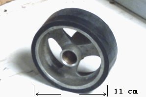
After re assembly of the Card Reader, we discovered that 5 layers was just too much, so we had to sacrifice one layer of rubber ( now a spare layer ).
After final set up, we wound the card reader over by hand, and it fed a card down the track and into the stacker, thank god the timimg of the machine had not been lost.
However now we have discovered a simple fact, all that hammering away has caused us to loose the filaments in 4 out of 5 of the lamps in the photo_cams. Oopps.. ! So its hunt the 6 Volt 6 Watt bulbs time now.
Work on the CPU starts next visit !
35th Episode:-20/04/05
Some careful drilling today gave us a succesfull removal of the taper pin holding the stacker drum bevel gear. The result is that we have been able to take the drum assembly, off of the machine and can now review the chance to repair. The best bet for the stacker drum is to use layers of car inner tube to build the surface up to the required depth, this will be used in place of the original neoprene moulded surface.
The third feed rolls are a different problem and we have elected to make nylon tyres to replace the original neoprene surface.
We tried some Mylar tape in the Tape Reader and it seems all the track amps are working, with all bit combinations bieng transfered into the B register from the Tape.
Some work now on the Tape Punch Mechanism, first the ability to feed tape and lace the mechanism up. Now O.K. However the Punch driving logic seems defective as it tries to punch all the holes all of the time, another problem to add to the list!
Very little work on the main CPU, this visit, which at least seems to be staying stable at present.
34th Episode:-06/04/05
Back to the mechanical problems on the card reader.
Now the taper pin problems are comimg to a head. the pin has already been replaced, sometime in Flossie's history and may not be lined up ! This could explain why it is not responding to considerable hammering, with pin punches! and we may HAVE to drill it out !
Examination of our "Spare" reader, shows the same decomposing rubber problems, so we agree that we must focus on the pinning problem first ! Work continues and the last rubber cable to the compressor is replaced, a test of the reader shows we have solved another problem and even the contactor worked first time, now we move onto the Line Printer !
This seems to be in a good state of preservation, well greased many years ago ! But more rubber mains cables are found, so work will need to continue here !
Attention now turns to the Paper Tape Reader, which has been blowing fuses when we tried it last year. The problem proved to be a mains filter, so the supply was re-routed via another source and then the reader was successfully powered up, we even managed to read a few characters into the machine from the read head !. Just to prove life still had a few downs we did blow a fuse, but after all those years, I think it was allowed to ! "Don't You?"
Attention turned to the Computer again, and we were happy to find it still behaved as well as last visit. We even managed to power up the Drum and read some of the data written during last years work. To be fair we also had some read failures but all in all the investment in work over the previous years are now showing in a more reliable computer.
33rd Episode:-23/03/05
The first visit of the year and its time to check out all the mechanics of the peripherals. So the Card reader has the following jobs to do, first the old rubber Mains Power cables have to be replaced, then we have to get the rest of the decomposing rubber components need to be sorted out. All the while whilst working on these items, the mind keeps wondering how much of the electronics have survived the winter hibernation.
But forcing our mind back on course we replace the internal cables within the card reader, and then discover the taper pins fitted to the reader drive shafts are solid, one in paticular will not drive out. Plans to drill the pin out prove just how hard this is going to be.
The day ended with us testing the wiring and checking that the three phase motors run in the correct direction. To do so we must power up the machine, we are greeted with a lot of the machine running and we are able to both make the reader ready and issue feed orders ( 380002 )
Now we cannot resist trying the computer out and putting it through its paces.
After some problems with the Contactor in the reader ( who knows when it last worked ) we discovered that the main computers Mill seems to be functional and even some store, enough of the machine seems to be running for us to code up " Ghost " a simple loop that confirms the mill functions including the hardware multiply.
This is a good sign after the years of work and we take it as a sign that all the work has not been in vain, Flossie has awoken from hibernation in "Not too bad a state".
Start of work in 2005
End of work in 2004
32nd Episode:-
Last 2004 session:-17/11/04
General tidy up day, lots of boards wrapped in then, a quick try of the machine, we now have started to get drum errors on reading decade transfers, and store parity errors on decade writes ! Is it the cold ? or do we have a new fault ?
Worked around the drum and could see on a single decade transfer the bits being written to the drum, but cannot see stabiltiy of the data during a decade read. In fact it can be seen dithing, relative to the read clocks, which suggests digit counters. Working along the line of digit times we were getting a lot of spurious pulses, unfortunatly this is typical of 1301 logic. As we were running out of day it was decided that we would close work this year as the low temperatue will stop us doing further fault finding, and could even be giving us more problems.
We now have what we belive is a corrected copy of the initial orders, we have recoverd from the Drum, but we will not rewrite these until we are sure we are writing good parity with the data.
So it was covers on and Flossie was put to bed for the Winter. We do seem to have come a long way since the start in 2003, however we still have a long way to go !
Check Back Soon !
31st Episode:-
More work on the drum and in an attempt to rectify the Channel Write's which are both giving us store parity on write and drum parity on read, however we can write individual decades with decade transfers and read a whole channel of individual decades back ok !
Just to keep us on our toes we had a failure in the control registers, with 4 bits bieng streamed from control register 1 to control regiter 3, this was a package in 5D26.
One of our biggest problem today was the fact that the programs loops were getting corrupted with the store parity errors. Trevor Chapman was with us today, and suggested that we move the code for the program loop up the store beyond the first two working store pages. Well done Trevor we no longer have a corrupted program, which means we can now fault find in a dynamic situation, which is just what you have to with this machine!
So the state of play is that we can write and read decades, Read a whole channel (20 decades), but cannot write a Channel due to store corruption when we try.
30th Episode:-
Today started with a failure in the first page or ( barndoor ) Bit 1 in Digit 2 failing, replaced the A7 package and then down to fault finding the drum some more.
Continued work on the Drum clocks to try to get a better copy of the initial orders code off of the drum, working on the theory that we could set the clocks to read the data as it was written.
The overview is now that we can read and write to both Normal and Reserved Bands, with Decade transfers, ( block of 10 words ). We can also read 20 decades with a Channel transfer, but cannot Write a channel to the Drum
29th Episode:-
Today is designer day ! Follow this link for news of the day
Desinger DAY News and Pictures
28th Episode:-
Rogers Worked alone this time on a Sunday and isolated the cause of the Channel transfer problem, I am advised that the Channel read now works !
And yes it does !
27th Episode:-
A lot of today was spent in capturing the content of the reserved bands, this has been done by a small piece of code in the 1301 which transmits, an RS232 format signal to a PC connected via the output of a programmed indicator. A simple TTL to RS232 level conversion is applied and the PC functions in "Capture Mode"
Work was halted whist we repaired digit 9 bit 1 in store page 1, a new A7 package solved that problem
During emails which followed the day, Roger confirmed that with a bit of tinkering, we have a ( possible? ) working copy of I/O's ( At last ! )
26th Episode:-
more Drum mayhem, but we do seem to be winning, we now understand that if we choose the orders in the control registers with care we can even set up a small loop of code in the store and not get it wiped each time we try to fault find.
Using this we have isolated our problem to closeure of the Drum order and signal R6, the drum order runs into the start up of the main machine, at that point the drum is driving the control registers and the machine is trying to obey the next instructions. Nasty things result !
If we keep the following instructions limited to STOP orders we seem to have some control over the situation. Attempts to fault find Micro order by Micro order all fail due to the loss of synchronisation to the drum. Ultimately our investigation of the day took us to bay 11 and fault finding around this area was proving, eerrrrr! Touchy ! If we touched anything in the area different things happened! most of the logic in level B seemed to have corrosion around the logic boards and the connections.
So we took a dynamic decision when Roger produced from our pile of spares a complete replacement rack. During this removal and replacement the remains of a birds nest was removed from the rest of the logic, I do wonder if we will find more oddities like this as we progress through the project. The new rack gave us a more stable situation but essentialy unchanged problems, we know we are in the right area but we can only remove one problem at a time and keep going.
The upshot of today is that I have suggested that Roger makes soup this evening, YES, BIRDS NEST SOUP, of course !
25th Episode:-
For this session it was back to the drum problems which continue to dog us and we have isolated some of the issues in resolving the current problems. The machine will do different things depending on what is in the third control register when a drum order is issued. we can now predict what will happen ( mostly ) and have isolated the problem to what we suspect is " Running on ", the drum order completes, but the control is not passed back to the main machine and the control registers keep spinning and adding up the drum order until we FALL off the end of the working drum. The main signal which seems to be set for too long is R6 this should only be up for ten times one word. ie: 52 micro seconds times ten = 520 plus a few microseconds for the setup and close down of the drum order, but it is set for at least twice as long and maybe more.
We do however have an advantage, we have the storeage oscilloscope back after its repair. We have sorely missed this valuable tool, and now although we have to check signls running from one side of the machine to the other we can see even single pulses and analyse them. So isolation of signals in the function mesh, to try to trap the END micro order duration, started. Soon bay 3 looked busy with isolators in 3E6 pin 7, 3E6 pin 6, 3E12 pin 14, 3E14 pin 12, 3E16 pin 9 and 3E23 pin 4. This was to identify when the drum order which uses the T5 signal changes to T3, to signify the end of the drum order.
We closed activity today feeling somewhat defeated, but closer to the definition of just what the problem was to start with!
However a high point today was the finalisation of a simple piece of software which uses a programmed indicator to send RS232 signals out of the machine.
WHY ? to unload flossies software
HOW ? to send Store, and hopefully Drum and Tape data, to a laptop and archive it !
WHEN ? I do wish you had not asked me that ! ( for the answer is:- when we get the Drum Working )
24th Episode:-24/8/04
At start of this session Roger has cleaned up the logic gating around the gereration of " Q times " these are the main 1 mhz clock divided down to 250khz and split into 4 quarter or "Q" pulses. our slip pulse problem remains however, and was finally isolated to 11F9 , the defective Binary was replaced and now we have both an alarm and syncronisation to the drum.
The big try " Our first Drum order " the Control registers were set up as 830100-010700 and with fingers crossed start was pressed. SOMETHING HAPPENED, but what ? We did not get the result expected and no data came from the drum, but the control registers showed, that we had tried to count the tranfer through the registers. A deeper analysis showed that the machine had stared the tranfer but was unable to find the address on the drum. The drum is devided into 20 " Decades " around the circumference and this is mapped out in the digit, word and Decade counters. The coincidence with the required address was not bieng detected correctly and fault finding found 11D7, pin 13 , also 11A22 not working. Now we have a drum transfer that completes, still no valid data transferd to store, but we are getting something from the drum which is overwriting the old store contents. A further problem seems to be that we are transfering only half of the decades we request, this was tracked down to the decade counter bieng counted twice each transfer so 11A6 pin 14 fixed this.
Now somethimes we feel we have won a major battle with this project and this was one of those moments, as Roger proudly reminded me we were now further forward than we had ever been since the project started. On the other hand sometimes flossie pulls problems and tricks out of the hat which we do just not see coming ! This was also one of those days.
On setting up a drum transfer of 810000-010000 ( transfer just 10 words into store from the start of the drum ) and pressing start we were greeted with a machine that went " Very Busy !" the final end to which was that the machine stopped with 816101-010601 in the Control registers and we had transfered all of half of a drum into the store about 3 times over, and all of the store had been wiped of our software and replaced with random data from the drum.
So flossie has gone from Not-Starting to Not-Stopping in one step.
Today closed with us feeling we had just won, and then lost any advantage we had gained from our work. As we now could not put any tests into store to test the drum, as flossie would wipe any software as soon as we pressed start.
23rd Episode:-18/8/2004
The work this session started with finalising the drum setup, all of the work so far has been a prelude to this point, for without the drum we have no where to store any software. Even small test loops have to be input by hand, and are lost at power down, so drum store is vital if we are to unload the historic software from this machine. The work to complete the tape control unit and fault find the data paths will also require some simple test software so all our effort focus now on getting the drum working !
the first set up was to check the gate which is only used for the drum reserved bands writing unit, but it has a counter output with the last bit of all of the counters. So ( Bit 2860 ) on 11D4 pin 22 was used to check the alignment of the clocks and the datum on both sides of the drum logic bays 11 and 12. Some considerable time spent on these to ensure as near perfect alignment, which has paid off since, due the the fact that we could be sure that future faults were not in this area.
A condition where the machine cannot stay in step with the drum still dogs this work however, the condition and error is called ( Slip Pulse ) and although we have fault found the whole chain of clock gennerating logic, the signal is still there.
For some light relief to end todays work we foucused on another problem where the multiply order has failed. This proved to be a defective gate in 6D4, pin 7 giving only a half level out, neither a logic one or a logic nought. Multiply now works, and the simple test of running " Ghost " proves all is ok.
22nd Episode:-18/8/04
First job of the day was to solder up the replacment mains connector for our damaged scope, We have been using an analog scope, during the period that this storeage scope has been down and I now miss its facilities very much. We are trying to work around the drum logic and trying to see a single pulse, one micro second long every 11.5 milli seconds is a challenge to an analog scope I assure you, but I hope the repairs will be completed soon.
Clock setup time again, this time some success and a stable datum pulse was extracted for each drum revolution, without this the various counters which time the data off the drum cannot syncronise to the drum and data would never be decoded properly. a trip along the digit counter showed a stuck two bit in 11A22 ( T1 package changed ) then on to the word counter. This was stuck and not counting at all, it was set to all ones and no clocking was taking place.
This counter is driven by two clock sources, the main one drives the counter once per digit the second one only sets the initial state of the counter, and it was the initial state that was not bieng set. Some time spent here scoping around as after changing the first clock gate in 11B19, also did gate in 11A1, did not change fault, as I had the same condition. It was not until I jumpered both sources together and saw the word counter start, that I realised the replacement clock gate was also not working, so a second package in 11B19 did eventually give us a working word counter. And a bonus ! We now have an alarm tone on the console speaker. We have not had an alarm tone that I can rememeber for a long while, so on we ploughed, the decade counter was now running as well as the word counter so hopefully we now have the ability to try to fault find the rest of the logic.
Some observations at this point:- the drum count signal does clear, after switch on, slip pulse ( clocking error ) does not, so it is back into the modified area of the drum. First test was to just listen to the alarm tone and trip the drum drive motor, the alarm signal followed the decreasing speed of the drum for an impressive period of time. This was a simple test but it proved the modified clock was working. Now the problem was to find which signal was giving SLIP PULSES ( or drum clocking errors ) . Sources are 11F19 ( pin 24 ) Isolated, 11F23 ( pin 24 ) also isolated, no more SLIP PULSES. This confirms that the drum clocking is still not perfect.
So into the clock checking logic and changed 11F18 and 11G8, this is part of the Q time counter and the waveforms around here dont look good, whilst changing the above boards it was found that the bistable in 11G8 was very selective as to what boards would or would not run in this position, at one point the precious alarm signal also stopped, so I know we are in the right area.
The day ended with a decision that we have too many boards on rubbers ( again ) and the next session must start with a tidy up and, checkinf that the micro orders work for other functions before we risk fault finding the rest of the drum transfer logic .
21st Episode:-4/8/2004
Some dropout and gaining on punching, we have put an earth to the punch frame, from the Zero Volt braid, and will have to test the reliablility at a future date.
A brief investigation into the MOVE or 45 Command counting too many words, stopped when the problem vanished during investigation, this was around the decade counter logic, also used by the Drum logic. So having been lead here now it is time to enter the complexity of the DRUM Clock logic once more !
Most of this visit, spent chasing our tails, around bay 11, 12 and 6. ( the trip to bay 6, was to change the ( first micro order on ) bistable in 3B16) No positive result from our efforts other than, we have eliminated the folllwing ! The clock, and Datum track itself ! ( have used spares ! ) and changed the most relevent boards, 11E3 drum clock . The primary problem is that the counter which splits the incoming timing track into quater pulses Q1 thru Q4, has been modified, ( capacitors Soldered to the G1 gate package in 11G11 ) along with the clock source to the counter bieng modified, Also the timing generator has been replaced with a modern phase locked loop chip! ( this at least is still working ) The whole essembly has obviously all worked at one time, but is refusing to work again at present.
No Drum clock and Datum decoding = No drum = No Initial orders !
Finished the day with the discovery that we are getting far too many Datum Pulses Generated, ( we are only meant to get one per revolution of the drum ), work will continue on the next visit !
But we are working with an elderly analog test scope and it is not good enough to resolve some of the single pulses we are searching for on this problem. A feature of this problem is that we lack a stopped status alarm tone on the speaker, when the clock system is switched to the drum ( normal mode of operation ). This should be very relevent, but its significance keeps escaping me, all will be revealed when the problem is finally resolved.
20th Episode:-
Various problems with the card punch again, Cam's cleaned and very basic timing checked, many relay points, now a lot cleaner. The Punch tries to punch most data now, we may have a driver in Col 44 which will need to be replaced, however the capacitor's on the board, are not looking too healthy, so it may be a change components job to resolve.
Using some software Roger wrote we found the 380045 ( Check brush reading ) failed, found G3 package in 1B19 ( pin 4 ) U/S, replaced and now Ok !
19th Episode:-
Work after the open day restarted with a whole day being spent on the Card Punch, the problem was finally resolved to the coil of relay seven ( yes it had gone open circuit ), but we did have the right part.
The Diagram for the Punch and the Wiring in the Punch are very different, Relay 10 does not even exist, any more and wiring around relay 7 is very different
Further work went into ensuring the hold path for the ready circuit was clean and functional ! ( we also Lost our precious osciloscope at the end of this session ) a nasty smell of burning filling the machine room. Or should I say an expensive smell of burning ?
18th Episode:-
Two whole visit sessions were put to tidying the console end of the machine for the visits, along with limited work on the Card Punch !
Special visitor today = Stuart Fyfe, one of the original owners of Flossie ( Great to see him standing at the console once again ) he also lent us some dispaly material for the open day, " Nice one Stuart ! "
"Notes from the 2004 Open day "
17th Episode:-
Work continues on the Mag tape drives and now we have two ( working ) Transports
Both Deck B and D now work, and communicate with the Tape control unit.
With the two decks up and running, the place now starts to sound like a computer room of the 1960's ( Lots of noise ! ). To add to the Cacphony, we started to find out just what of the peripheral devices would and would not run.
But first, after an experience Roger had with the card reader, we checked the direction of the three phase motor's. Sure enough we had to reverse two phases at the main connection, I wonder what else will now start to run correctly, now this is resolved ?
The Line Printer looks as if it might run Ok ! But there is a lot of work in checking out its main's wiring and a long time will be spent setting up 120 print hammers to work, as well as muttering a lot as we set up the paper throw mechanism. ( yes SPRAG's ) for the initiated, are a pain, but we will have to visit that pain soon !
Also the drive motor turned the right way,the drive belt was refitted, and we were again rewarded with the sound of the machine doing a single card cycle. Some time was then spent clearing our first card wreak, from the feed path, and after that the punch settled down to its new life of work.
For the uninitiated, this was a big bit of luck. The punch gearbox is quite a complex piece of work, and owe's its ancestory to the original design of the Hollerith Card Punch, Card Reproducer ( Punched Card Copying Machine ) . That design in turn, is now over 60 years old as I remember working on Black painted machines with were marked " Lease Lend " from the Second World War years, these had the same essentail design !
Some in depth checking of oil levels in the gearbox followed, and now we have a working Card Punch. Now Eleveated by our good fortune, We started to Discuss SHOWING FLOSSIE OFF !
So We may be off of our tiny mind's, but Flossie will be open for Public View ( Working or Not )
on Sunday the 11th Of July 2004. Where the history of this machine will be explained to any
visitor's and access will be granted to view the Consul end of the machine. No promises,
BUT if Flossie decides she will run's on the day that will be a bonus !
The event which flossie will be viewable at is the
" Darling Bud's of May Classic Car Rally " at:-
Buss Farm Bethersden Kent, on the 11th July 2004
Just follow the signs on the day, and dont forget the *
Darling Buds Classic Car Show Buss Farm Bethersden Kent * is an Event not too be
missed Anyway, with so many dedicated car enthusiast's displaying with pride thier work
on Car's, which in some cases are older than Flossie's 40 Plus year's.
16th Episode:-
Investigation into access to magnetic tape transports:- Of the four Ampex Type 3 decks we have connected to flossie the attempts to power them up gave us the
following results:
Deck A = Tight / Locked lower servo motor ( investiage later )
Deck B = Loaded tape runs forwrds / reverse and responds to read, rewind and unload commands. ( Good Deck this one )
Deck C = Loads up tape, responds to rewind, and unload commands. No response to any other commands and just goes busy.
Deck D = Loads tape, has a servo problem with the upper reel
Drive and needs the forwrds Pinch roller assy adjusted.
tried to resolve the servo problem on the supply reel, but had to postpone
till next visit
So using the best deck from above, we investiagted just what we could and could not do with the tape control logic Attempts to read do not transfer any intelligent data into the machine but the transfers do finish and we tried to run a simple loop, which included testing the deck ready indictor, doing a read order, and repeating the loop. This ran perfectly provided we ran it one instruction at a time, in manual mode. However any attemts to run this in auto mode, gave us corruption of the program code. After much head scratching we found that we had isolated the Control register shift timers whilst fault finding last year, at 6E3 Pin 13. Restoring this gave us data input into store, blocks of about 120 words could be read in but the program corruption problem continued.
This problem has been traced to bay 22, where 22B23 pin 22 there is another level from the 1900 series standard interface signal comes in, isolating this gave us a reliable program loop, so we closed the day with a successful run of the following little loop !
With our one working deck allocated to deck address 3
000 = 834001 004000 ... / wait for Deck 3 Ready
001 = 724002 004000 ... / wait for read unit ready
002 = 390023 000400 ... / read a block into store at address 400
003 = 834001 004003 ... / wait for Deck 3 ready
004 = 724005 004003 ... / wait for read unit ready
005 = 390053 660100 ... / Rewind deck 3 and increment count
006 = 370100 004000 ... / display count in B Reg and loop back.
This loop reads a block, rewinds the tape and displays a count of how many times it has done the loop. We held our breath until the count had reached over 50 and then decided we had actually fixed the problem.
Next visit is with feeler gauges and allan keys to set up the rest of the Tape Decks. I felt very bouyed up as most of the tape control unit was working. But we still need to actually read the data from tape some time ! So we are getting ready for a battle with the DTU !
15th Episode:-12/5/2004
Continued work on store units:-
Barn Door 3 lots of differing errors
Barn Door 4 Acting dead.
Much work on this store including changing a G1 unit in 10E17 ( decoding unit ) until we finally located an addressing problem where decode 80/180 and 90/190 were both comeing up together. This seems to be within the structure of the door, and much time was spent tracing wiring on the printed circuit strip panels which run the length of the lower part of the core planes. Ended this session with a rather blank feeling as the progress had been zero. We still have Barn Doors 3 and 4 to fix.
Lots of boards are on temorary connectors in this barn door. However these two bard door's have never worked since the start of the project, so we have only to fix them once and hopefully they will stay fixed !
14th Episode:-
More work on store units and lots of data bits dropping out:-
Digit 7 Bit 1 + Digit 5 Bit 8 + Digit 7 Bit 2 all failing,
so much sorting of duff A7,s ( store read/write anps ) and we had reliable access to some store, with a duff -6.3 volt Fuse ( 20 amp ) blown on the way !
We are now down to a single duff word in barn door 2 ( much time spent wiring in the " SPARE " core word on the Store Plane ) after many tries we re-read the manual and remembered to wire in the ground connection to the spare address line, we now have a working second store unit. We can run a small loop of move ( 45 ) orders and the store does not give parity failures.
The day closed with us trying to run "Ghost" but we may have a problem with Function 69 ( multiply ) so ghost just produces a boring single note in the speaker. I bet this is micro orders again, but only time will tell !
13th Episode:-
Programed indicator tidy up!
We have had problems with two of the programmed indicators since this project started. Over a coffee before we started, it was decided that we would indulge ourselves and just fix these indicators, before we did any more work.
PI 11 turned out to be 7E9 binary u/s = replaced,
and PI 12 was the 7E10 binary , now all ok ! And a big boost to our confidence.
There are still problems with access to the store units, work around the IAS timing generator resulted in changing the Binary in 10E8 and Invertor in 10E9 these gave us correct IAS timing and timing signals W1 and W2 are now correct, Still no access to any store. Checked all voltages and found 18 volts unit fuse blown.
We can bow run a loop in the first barn door, Much jubilaton followed! we had access to Bard doors 1, 2 and 5 but word 518 in Barn door 2 was a solid fault.
12th Episode:-
The First Power up 2004 ( no smoke ! No big bangs ) But the machine is stuck in micro orders !
30 mins later, during which we checked all fans and power supplies. The system started to run, but with problems. Found Binary in 3B17 duff ( not adding one to Control register ) Now OK but still no access to store at all. Traced to 3E17 Pin 3 duff, also A1 package in 6F7 and G3 in 6F8, Now able to get some instructions into the control registers. Well as a start in 2004 it could have been worse, but we will have to get flossie back to where we left her last year.
Most of the things we fixed last year do seem to be working, so not a bad 1st day in 2004.
Start of work in 2004
End of work in 2003
11th Episode:-
The visit started with the standard sulk period when Flossie was turned on and was warming
up. We took the time to examine the half inch mag tape decks, looking along the line of
desks, for a deck that was working enough to try to load and run a tape. We will need to
do this soon as we plan to read the old tapes back and re populate Flossie's program library.
We found a deck that not only loaded and ran but also performed a stable and perfect rewind
at high speed, no wobbling servo arms, and a full parking of the arms at the end
of the rewind. We have one deck that works at least.
Flossie now runs a simple test called GHOST, this is as follows
0000 = 370100 220001 ... / Load B reg with contents of 100 , set Dec point Reg to 10001 = 690101 660101 ... / Multiply reg B by Content of 101 , increment Location 101
0002 = 294000 004002 ... / pulse the speaker if 29 set , else loop on 29 set
0100 = 000000 001248 ... / Fixed data
0101 = 000000 000001 ... / Incremented data
After this event with even more Jubilation, we continued the factory test suite to test number 4.3 this included a Sterling multiply, which worked first time.
10th Episode:-
Flossie warmed up quite quickly this time, but we soon found we had a new problem, as we were unable to obey any instruction which ended in 6 . ie 16,26,36,56,66 all dead. slowly traced down to package 3C19 us, We can now run test MI 26 or 66 functions ok. Factory tests continued till we reached 3.50 then we found that bit 1 of digit 8 in the B register was suspect, traced to T1 package in 2C14. Test 3.55 located the two bit in digit 7 of Register B, replaced 2D13. The machine is now running a loop and even obeying a move or 45 function. we tried the following
45 0000
19 0100
At the end of the day it was big smiles all round and we left feeling that we were winning. However those who know the 1301 computer, will tell you that there are all the Micro Orders yet to get working, or to put it another way. HELL WAS WAITING FOR US.
Last factory test completed this trip was 3.609th Episode:-
The first visit after I returned from a cruise, only Roger and myself this time, ( we missed having you around Tom ! ) work got under way to confirm we had access to some working store and the three stores still worked after a suitable warm up period. We started to work through the initial factory tests and found several problems. A G3 package in 3C1 part of the function decode was giving us 80 ( drum ) instructions when none were there. Replacing that board allowed us to have stops and non valid function decodes again, also the CR1->3 signal now worked. Further decoder faults were spinning the pulse generator the wrong number of steps and giving spurious results. Some fun was had locating the sterling position counter and the decimal point register. However the real problem here was that two bits of the decimal point register, were shorted together, of course the short was under a cover, after removing the cover, a thump was heard as Roger sprung the pins apart, another solid engineering solution applied. A further problem which gave us a big surprise was the setting of the main stopped ( P3 ) binaries, this gave an odd symptom when we were in the area of the fault. The logic levels on a 1301 are zero volts for a logic zero and -6 volts for a logic one. But this fault gave us + 5 volts on some logic pins, this was eventually traced to unwrapped pins on the earth supply to the G1 gating package in 6F21. Resolving this gave us the ability to actually get the machine into run mode. The end of the day we took to wrapping in a lot of the outstanding boards left on rubbers, this took some time and when we powered up, the machine took a long while to overcome its cold faults, of course we blamed the work we had just done. So it was with great relief that the machine finally started to shift its Control Registers again, after the warm-up and to finish the day we ran our first multi instruction loop. All of two words in store in locations zero and one. The loop did not work correctly, but it did run the instructions and the stopped lamp went out whilst this was running. This is the first time flossie has obeyed any stored instructions in many a long year. last factory test completed this trip is No 3.31.
8th Episode:-
This visit started with the news that we had received another wrapping tool, Thanks to Mike Trueblood. So we were able to do a lot more in the time we had today, Tom was along again and proved the new wrapping tool worked well around Bay 5, with a couple of Control register bits in 5F20 and 5F21, also the clock amp. Some outstanding parity problems were removed from BD0, A7 in RD1 replaced. Problems with store selection were further resolved when we found an unwrapped pin on 10E16 pin5 ( how long has that been unwrapped ?? ). Further work on store selection resulted in us replacing 10E6. At the end of the day we had 3 out of 5 store units ( Barn Doors ) working, Numbers 3 and 4 still not playing the game. Time was allocated at the end of the day to do some serious wrapping in , 8 boards in the barn doors, and 6 more in Bay 5. It was a lot easier now we have two tools. The day also saw the test drive of another tool which starts to solve a problem we found at visit 6, namely the breaking of board rubbers, pure age as the rubber gets less flexible. We tried a home made solution of a modified wallpaper scraper, it works, and puts less strain on the 25 way rubber connector. Progress ( of sorts ) today .
7th Episode:-
This visit we welcomed to the project, the skills of Tom, who popped over to see what we were doing and in no time, was wrapping in boards like the old days, so 3E21 was Toms' donation to the work. Just then Reg 'A' decided to blow up bit one of Digit nine, T1 in 10A8 replaced, before it worked again. We were able to make some progress today as the machine started with a 'sulk' ( needed to warm up ) then started to give us some progress. We were able to talk to the first 400 words of IAS ( with some bit drop outs, of course ). But only after we removed an enhanced decode for an address greater than 2000 words, by isolating the additional address binary. Then we were able to talk to the second 400 words, so from 000 to 799 words were trying to work, they worked even better when we changed IAS read amps in BD1/D3B2, BD2/D10B1, BD2/D2B8, BD2/D3B8, also the T1 in 9D22 and the T4 in 9B6 whilst we were fault finding. To get the rest of the IAS working words 800 to 1999 will need to be worked on though.
6th Episode:-
Work on 8 bits dropping out in CR's , around T1's in locations 5F21,24 and 26, had to swap these more than once, as the boards we replaced these with, were causing more problems, eventually got reliable CR one, two and three streaming, although this still needs testing at full speed. Continued with System runaway problem, this machine has always seemed to be 'BUSY' IAS Parity lights running and DTU doing things at odd times, we often find that there are extra signals around the A register when working on problems, The DTU read and write logic was investigated in the 4th Visit, and were found to be steady and going into default status at switch on/off. Which only left the possibility that the machine was fitted with a 1900 Tape interface, which was defective. This was investigated and yes it was running away, we worked on this for about half an hour and decided that it was quicker to isolate the signal causing the DTU to request transfers, and solve the source at a later date, this would allow us to work on the basic machine and resolve the primary problems. Pins 9J15 and 9J25 ( both pin 21 ) were isolated. Suddenly Flossie no longer had a headache, the DTU was no longer busy and we could re-asses the basic machine problems. The good news was that all the Programmed Indicators now work ( most of the time ) Some basic functions were tried and Function 57 seems to be reliable also 54 works, we then got greedy and tried a 42 function, it failed so we tried a 37 instead, no joy again but we have not worked on the IAS Yet. Next step was into the function decodes, after a lot of signal checks found 3E21 board duff. ' Blast it we changed that on the first visit ' so it was changed again. At the end of the day we were happy that a major problem had been isolated, and we could now pursue the basic machine problems. Although we have reduced the number of boards on rubbers we 'MUST WRAP IN THE REMAINING BOARDS STILL ON RUBBERS' ! There is also a problem with the rubbers themselves, as time is now starting to reduce the flexibility and some cracking can be detected at the moulded joints. A solution may need to be found to this soon.
5th Episode:-
Dropping Bits in CR one, two and three, and unable to spin the Control registers and do basic plus one between CR one and three. So changed the following list of boards whilst investigating: T1's in location 11G22, 5E26 and 5E17, G1's in 5B13, 5B15, 5B16 and 5B17 also board in 5F23. We can now do a plus one up to the value of 7 then we drop the 8 bit and start again. We have changed lot of boards this time round and the number of rubbered boards in the machine is growing. WE MUST WRAP IN THE LARGE QUANTITY OF BOARDS NOW ON RUBBERS !
4th Episode:-
Work continued on the CR1 to CR3 problems and the decode of Non Valid Functions, i.e. STOP instructions now works, this was traced to a T1 in 6C10. The system now looks as if the main processor is being stopped all the time, some rechecking of the previous, repair confirmed that now we had allowed the decode the CPU was being held stopped by the Data Transfer or Tape Control unit. Starting with the Address Book we found that the signal we wanted ran between bays 4 and 9 at 6DR2 pin 17, checked out signal as ok there, so considerable investigation followed, including checking the status of the Read Control unit and the Write Control unit in the DTU. At one point we had isolated no less that five individual pins on a counter feed back loop only to discover that the counter was a a digit counter and the real status registers were in the next bay. It was however proved that the read and write control units did set to the correct status at power up, which means we have interface control problems. Another board popped during the power up/down sequences, whilst investigating the above, an A1 in 13E12. So work continues at the next visit to ensure the DTU is not interfering with the CPU so we can do basic fault finding.
3rd Episode:-
Assorted problems at switch on are CR1 to CR3 gaining 2 bits investigated and A4 in 13E13 replaced, cured this fault. We also had failing to add one to completed instructions. To resolve this later problem, the clocking of the control registers was investigated, unfortunately the investigations were with an oscilloscope which I was unfamiliar with, and the result was that I wasted some considerable time, chasing my own tail. However the lesson has been learnt and we wont make that mistake again. The clock source on flossie has been modified, and the impact on the logic with the drum resynchronization is that whole chunks of the logic have been removed only a single board in 11E15 remains of the original logic. This was brought home to me when I opened the console to discover that the variable clock module, had been completely replaced. There was just a potentiometer, where the module used to be. It has since been verified that the clock source is good, just different !
2nd Episode:-
Before power up, it was decided we needed to check all the cooling fans, so the machine was ready for the warmer weather. Some units were beyond simple repair, with burnt out windings. However the majority of fans responded well to stripping down and lubrication of the bearings, work then started on existing faults. Some problems had been identified with the shifting of the Control Registers and after investigation the G1 in 5B9, was changed to allow the CR's to rotate without corruption. Work on the display selectors ( big bank of relays ) and the setting encoders continued until we ran out of time. However the majority of the displays, and setting bits now work.
1st Episode:-
This was mostly spent learning what the situation was, the state of the machine, the suitability of spares. However some time was spent in trying to resolve the multiple faults on this elderly machine, and the board in 3E27 and in 3E21 were changed to cure a fault where the Pulse Generator terminated early on all orders.
Start of work in 2003
